2002-6401 WAGO, 2002-6401 Datasheet - Page 57
2002-6401
Manufacturer Part Number
2002-6401
Description
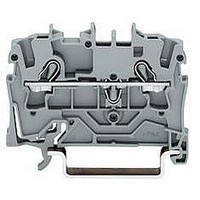
TERMINAL BLOCK, DIN RAIL, 4POS, 22-12AWG
Manufacturer
WAGO
Datasheet
1.2002-6401.pdf
(98 pages)
Specifications of 2002-6401
Connector Type
DIN Terminal Block
Connector Mounting
DIN Rail
No. Of Contacts
4
Wire Size (awg)
22-12
No. Of Positions
1
Terminal Block Clamp Type
Cage Clamp
Current Rating
20A
Color
Gray
Rohs Compliant
Yes
Lead Free Status / RoHS Status
Lead free / RoHS Compliant


** AWG 12: THHN, THWN
*
PCB Terminal Strips for THR Soldering
Series 236 and Series 250
Pin spacing 5/ 0.197 in
0.08
200 V/4 kV/3, I
320 V/4 kV/2, I
L 5 – 6 mm / 0.22 in
U
No. of
poles
Terminal strips, reflow soldering technology,
2 solder pins / pole, black
2
3
4
5
6
Other numbers of poles and pin spacings on request
Accessories
Double savings are now available with WAGO
PCB terminal blocks: as always, the time-saving
CAGE CLAMP
now additional savings from their suitability for
the THR solder process. This is achieved by
changing the length of the solder pin which is
adapted to the reflow process and by the use
of high temperature resistant plastic for the
insulating housing.
The new terminal blocks are simply pushed into
the solder paste filled PCB holes and then sol-
dered along with the SMT components. The
previous wave soldering process is no longer
necessary. The result is a perfect connection
both from the mechanical and the electrical
point of view.
Dimensions
L = (No. of poles x pin spacing) + 2.3 mm
Diameter of metal plated hole 1.1
optimised for PCB width of up to 2 mm
– 2.5 mm
<___14___>
>
5
Item
No.
236-402/334-604
236-403/334-604
236-404/334-604
236-405/334-604
236-406/334-604
®
(in mm)
5
and push-wire connections and
N
N
<
2
16 A
16 A
Operating tools
Plastic
Metal
> 3,5
<____________L____________>
>
for factory wiring
AWG 28 – 12 **
300 V, 15 A U
<
5
+0,1
<
236-332
236-335
mm
Pack. unit
pcs
420 (4 x 10⁵)
280 (4 x 70)
220 (4 x 55)
160 (4 x 40)
140 (4 x 35)
,
> <___
0,7
1
1
*
Pin spacing 2.5 mm / 0.098 in
0.4
250 V/2.5 kV/2
I
l 8.5 – 9.5 mm / 0.35 in
U
No. of
poles
Terminal strips with push-button, reflow soldering
technology, 1 solder pin/pole staggered, black, with
test slot for test pin up to 1.3 mm Ø
2
3
4
5
6
7
8
Other numbers of poles and pin spacings on request
Packings for pick and place applications on request
N
2 A
<____12____>
L = (No. of poles x pin spacing) + 1.5 mm
Diameter of metal plated hole 1.0
optimised for PCB width of up to 2 mm
0.2 mm
– 0.8 mm Ø
<5>
0,4
<__
2
– 0.5 mm
2,3
( _
Item
No.
250-402/350-604
250-403/350-604
250-404/350-604
250-405/350-604
250-406/350-604
250-407/350-604
250-408/350-604
<
2
Test pin, Ø 1 mm/0.039 in
735-500
Test wire for sold. onto test plug
1,3
__>
“s”
“f-st“
<________ L _________>
55
<__
AWG 26 – 20 “sol.”
300 V, 5 A U
2,5
0,75
____>
+0,1
mm
<
Pack. unit
pcs
720 (4 x180)
520 (4 x130)
400 (4 x100)
340 (4 x 85)
280 (4 x 70)
240 (4 x 60)
220 (4 x 55)
___
first
solder pin
1
*
Pin spacing 3.5 mm / 0.138 in
0.5
400 V/4 kV/2
I
l 8.5 – 9.5 mm / 0.35 in
U
No. of
poles
Terminal strips with push-button, reflow soldering
technology, 1 solder pin/pole staggered, black, with
test slot for test pin up to 1.3 mm Ø
2
3
4
5
6
7
8
Other numbers of poles and pin spacings on request
N
2 A
<____12____>
L = (No. of poles x pin spacing) + 1.5 mm
Diameter of metal plated hole 1.0
optimised for PCB width of up to 2 mm
–1.5 mm
<5>
<__
0,4
<
2,3
°
Item
No.
250-202/350-604
250-203/350-604
250-204/350-604
250-205/350-604
250-206/350-604
250-207/350-604
250-208/350-604
<
2
“s+f-st“ AWG 20 – 16 “sol.“
Test pin, Ø 1 mm/0.039 in
735-500
Test wire for sold. onto test plug
<_____________ L _____________>
>
3,5
0,75
___> <
300 V, 5 A U
<
+0,1
mm
Pack. unit
pcs
560 (4 x 140)
400 (4 x 100)
300 (4 x 75)
240 (4 x 60)
200 (4 x 50)
180 (4 x 45)
160 (4 x 40)
1
1,75
___>
first
solder pin
___
<
1
Related parts for 2002-6401
Image
Part Number
Description
Manufacturer
Datasheet
Request
R


Part Number:
Description:
TERMINAL BLOCK, DIN RAIL, 6POS, 22-12AWG
Manufacturer:
WAGO

Part Number:
Description:
HOLDER BATTERY 4CELL D ALUMINUM
Manufacturer:
Keystone Electronics
Datasheet:


Part Number:
Description:
4 CHAN DIG INPUT 5VDC .2mS
Manufacturer:
WAGO
Datasheet:

Part Number:
Description:
Series 200 Switches Toggle Switches - Sub Miniature
Manufacturer:
e-switch
Datasheet: