2002-6401 WAGO, 2002-6401 Datasheet - Page 60
2002-6401
Manufacturer Part Number
2002-6401
Description
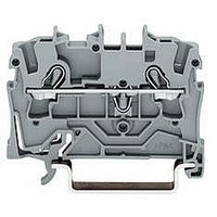
TERMINAL BLOCK, DIN RAIL, 4POS, 22-12AWG
Manufacturer
WAGO
Datasheet
1.2002-6401.pdf
(98 pages)
Specifications of 2002-6401
Connector Type
DIN Terminal Block
Connector Mounting
DIN Rail
No. Of Contacts
4
Wire Size (awg)
22-12
No. Of Positions
1
Terminal Block Clamp Type
Cage Clamp
Current Rating
20A
Color
Gray
Rohs Compliant
Yes
Lead Free Status / RoHS Status
Lead free / RoHS Compliant


1
* Further approvals with corresponding ratings can be found at www.wago.com
*
2-Conductor Female Connector Strips 1.5 mm
Pin Spacing 5 mm/0.197 in, Series 806
Pin spacing 5 mm / 0.197 in
2 x 0.2 –
250 V/ 2.5 kV/3
I
l 9 – 10 mm / 0.37 in
U
No. of
poles
Female connector strips, grey
for solder pin strip
10
11
12
For other lengths, please contact factory
Additional item numbers for colored terminal strips
blue
orange
Accessories
Solder pin strip,
Marker card,
1 – 16 (160 x)
Direct printing on request
Dimensions
N
2
3
4
5
6
7
8
9
<____19,8 _____>
10 A
1.5 mm
___>
2,75
(in mm)
<
2
Item
No.
806-102
806-103
806-104
806-105
806-106
806-107
806-108
806-109
806-110
806-111
806-112
. . . /000-006
. . . /000-012
connector pin Ø 1.3 mm
solder pin Ø 1 mm
2 to 12 poles
806-902 to 806-912
with self-adhesive
marker strips
210-332/0500-0202 1 card
>
<___________ _L ___________>
<___
Diameter of drilled hole: 1.3 mm
1,5
2 x AWG 24 – 16
300 V, 10 A U
>
5
•
2,8
<
*
Pin spacing 5 mm / 0.197 in
2 x 0.2 –
250 V/ 2.5 kV/3
I
l 9 – 10 mm / 0.37 in
U
No. of
poles
Female connector strips with removal aid, grey
for solder pin strip
10
11
12
For other lengths, please contact factory
Additional item numbers for colored terminal strips
blue
orange
Solder pin strip,
Marker card,
1 – 16 (160 x)
Direct printing on request
N
2
3
4
5
6
7
8
9
<____ 19,8 _____>
10 A
L = No. of poles x pin spacing + 1.5 mm
1.5 mm
2,75
___>
2
<
Item
No.
806-202
806-203
806-204
806-205
806-206
806-207
806-208
806-209
806-210
806-211
806-212
. . . /000-006
. . . /000-012
connector pin Ø 1.3 mm
solder pin Ø 1 mm
2 to 12 poles
806-902 to 806-912
with self-adhesive
marker strips
210-332/0500-0202 1 card
>
58
<___________ _L ___________>
<___
2 x AWG 24 – 16
300 V, 10 A U
1,5
2
/AWG 16
>
5
•
2,8
<
Connection of solid conductors:
insert stripped wire up to the stop
Connection/disconnection of fine-stranded
conductors:
open clamping unit using a screwdriver and insert
stripped wire up to the stop
Connecting the conductor directly into the connector . . .
. . . or pre-assembled
Removing the terminal blocks to place the board
Terminal strip insulation housings mixed in different
colors on request
A = (No. of poles - 1) x pin spacing
B = (No. of poles - 1) x pin spacing + 4.8 mm
(see also Full Line Catalog W4 Volume 2,
Section 12)
2.5 kV = rated surge voltage
25 0 V = rated voltage
> <____
> <___
3 = pollution degree
Ø 1,3
Ø 1
<___________ _B _ __________>
< _5_ >
<________A_______>
Related parts for 2002-6401
Image
Part Number
Description
Manufacturer
Datasheet
Request
R


Part Number:
Description:
TERMINAL BLOCK, DIN RAIL, 6POS, 22-12AWG
Manufacturer:
WAGO

Part Number:
Description:
HOLDER BATTERY 4CELL D ALUMINUM
Manufacturer:
Keystone Electronics
Datasheet:


Part Number:
Description:
4 CHAN DIG INPUT 5VDC .2mS
Manufacturer:
WAGO
Datasheet:

Part Number:
Description:
Series 200 Switches Toggle Switches - Sub Miniature
Manufacturer:
e-switch
Datasheet: