2002-6401 WAGO, 2002-6401 Datasheet - Page 68
2002-6401
Manufacturer Part Number
2002-6401
Description
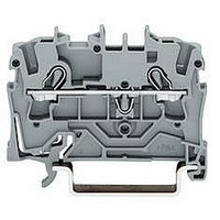
TERMINAL BLOCK, DIN RAIL, 4POS, 22-12AWG
Manufacturer
WAGO
Datasheet
1.2002-6401.pdf
(98 pages)
Specifications of 2002-6401
Connector Type
DIN Terminal Block
Connector Mounting
DIN Rail
No. Of Contacts
4
Wire Size (awg)
22-12
No. Of Positions
1
Terminal Block Clamp Type
Cage Clamp
Current Rating
20A
Color
Gray
Rohs Compliant
Yes
Lead Free Status / RoHS Status
Lead free / RoHS Compliant


5
* Further approvals with corresponding ratings can be found at www.wago.com
*
Dimensions
MULTI CONNECTION SYSTEM MINI
Headers with Solder Pins,
100 % Protected against Mismating,
Pin spacing 3.5 mm/0.138 in,
250 V/2.5 kV/2
I
U
No. of
poles
Headers with solder pins,
100 % protected against mismating, black,
straight solder pin 1 mm x 1 mm,
length of solder pin 2.4 mm/0.094 in
10
12
Accessories
N
2
3
4
5
6
8
10 A
L = (No. of poles – 1) x pin spacing + 5.9 mm
2,8
__>
__ _>
3,5
<______ _ L_ ______>
<
<
Diameter of the plated through hole: 1.4
Item
No.
734-132/105-604
734-133/105-604
734-134/105-604
734-135/105-604
734-136/105-604
734-138/105-604
734-140/105-604
734-142/105-604
(fit after soldering)
< >
1x1
>
Coding key, light grey,
snap-on type
734-130
<_ _
3,1
300 V, 10 A U
black
Reflow Soldering
*
Pin spacing 3.5 mm/0.138 in,
250 V/2.5 kV/2
I
U
No. of
poles
Headers with solder pins,
100 % protected against mismating, black,
straight solder pin 1 mm x 1 mm,
length of solder pin 2.4 mm/0.094 in
Headers in tape on reel acc. to IEC 60286-3
Reel diameter 330 mm /13 in
10
12
200 pieces per reel
N
2
3
4
5
6
8
+ 0, 1
10 A
mm – optimized for PCB thickness up to 2 mm
Item
No.
734-132/105-604/997-405
734-133/105-604/997-405
734-134/105-604/997-405
734-135/105-604/997-405
734-136/105-604/997-407
734-138/105-604/997-407
734-140/105-604/997-407
734-142/105-604/997-407
Pin Spacing 3.5 mm/0.138 in
<20>
Coding key, light grey,
snap-on type
734-130
66
300 V, 10 A U
Width of
reel (W)
black
(mm)
32
32
32
32
56
56
56
56
For use in reflow soldering processes in
convection ovens based on EN 61760-1
Note: These connectors can only be
mated and unmated at voltages
below 42 V and in the “No load”
condition.
For mating and unmating at low power
values, please request data.
apply solder paste
place components on PCB
begin reflow soldering process
Related parts for 2002-6401
Image
Part Number
Description
Manufacturer
Datasheet
Request
R


Part Number:
Description:
TERMINAL BLOCK, DIN RAIL, 6POS, 22-12AWG
Manufacturer:
WAGO

Part Number:
Description:
HOLDER BATTERY 4CELL D ALUMINUM
Manufacturer:
Keystone Electronics
Datasheet:


Part Number:
Description:
4 CHAN DIG INPUT 5VDC .2mS
Manufacturer:
WAGO
Datasheet:

Part Number:
Description:
Series 200 Switches Toggle Switches - Sub Miniature
Manufacturer:
e-switch
Datasheet: