2002-6401 WAGO, 2002-6401 Datasheet - Page 65
2002-6401
Manufacturer Part Number
2002-6401
Description
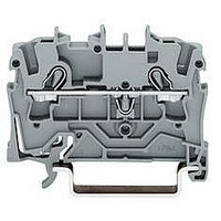
TERMINAL BLOCK, DIN RAIL, 4POS, 22-12AWG
Manufacturer
WAGO
Datasheet
1.2002-6401.pdf
(98 pages)
Specifications of 2002-6401
Connector Type
DIN Terminal Block
Connector Mounting
DIN Rail
No. Of Contacts
4
Wire Size (awg)
22-12
No. Of Positions
1
Terminal Block Clamp Type
Cage Clamp
Current Rating
20A
Color
Gray
Rohs Compliant
Yes
Lead Free Status / RoHS Status
Lead free / RoHS Compliant


*
Y
Terminal Strips 6 mm
Pin Spacings 10 mm/0.394 in, 12.5 mm/0.492 in and 15 mm/0.591 in; Series 745
Pin spacing 10 mm / 0.394 in
0.2
630 V/8 kV/3
I
L 11 – 12 mm / 0.45 in
No. of
poles
Terminal strips without fixing flanges, grey,
with spacers
2 solder pins /pole
10
12
Additional item no. for terminal strips with fixing
flanges
For assemblies in other lengths and colors, please
contact factory.
Dimensions
N
2
3
4
5
6
7
8
9
Diameter of drilled hole: 1.8
L = (No. of poles – 1) x pin spacing + 7 .5 mm
L1 = L + 1.6 mm
<_____29,1_____>
32 A
Using jumpers, the UL current is reduced to 10 A at
pin spacing 10 mm
– 6 mm
>
_) <__
( _12,5_ )( _8_ )
10,2
4,2
13
(in mm)
2
= ^
<
without fixing flanges
Item
No.
745-1352
745-1353
745-1354
745-1355
745-1356
745-1357
745-1358
745-1359
745-1360
745-1362
. . . /005-000
>
_ _
0,9
9,1
<
(9,2)
(
<
>
Mounting shall provide flexibility for the PCB.)
+0. 1
AWG 24 – 10
300 V, 10 A
<______L1______>
<______L______>
<
7,5
mm
<___
4,15
< > 10
>
1,4
__ >
10
Pack.-unit
pcs
104
72
48
40
32
24
24
16
16
16
<
2
>
9,2
< _
/AWG 10 with Spacers
< __ _
8,2 <
Y
1,6
<
*
Y
Pin spacing 12.5 mm / 0.492 in
0.2
800 V/8 kV/3
I
L 11 – 12 mm / 0.45 in
No. of
poles
Terminal strips without fixing flanges, grey,
with spacers
2 solder pins /pole
10
12
Additional item no. for terminal strips with fixing
flanges
For assemblies in other lengths and colors, please
contact factory.
N
2
3
4
5
6
7
8
9
<_____29,1_____>
Diameter of drilled hole: 1.8
L = (No. of poles – 1) x pin spacing + 7 .5 mm
L1 = L + 1.6 mm
32 A
Additional item nos. for colored terminal strips
and end plates
blue
light grey
green-yellow
light green
>
– 6 mm
Suitable for Ex i applications
_) <__
( _12,5_ )( _8_ )
10,2
4,2
13
2
= ^
<
without fixing flanges
>
Item
No.
745-1402
745-1403
745-1404
745-1405
745-1406
745-1407
745-1408
745-1409
745-1410
745-1412
. . . /005-000
_ _
0,9
. . . /. . . -006
. . . /. . . -009
. . . /. . . -016
. . . /. . . -017
63
9,1
<
(9,2)
<
>
+0. 1
<_______L1_______>
<_______L_______>
<
AWG 24 – 10
600 V, 30 A Y
7,5
<___
mm
4,15
< > 12,5
>
12,5
1,4
__>
Pack.-unit
pcs
<
>
9,2
< _
< ___
8,2 <
1,6
<
*
Y
Pin spacing 15 mm / 0.591 in
0.2
1000 V/10 kV/3
I
L 11 – 12 mm / 0.45 in
No. of
poles
Terminal strips without fixing flanges, grey,
with spacers
2 solder pins /pole
10
12
Additional item no. for terminal strips with fixing
flanges
For assemblies in other lengths and colors, please
contact factory.
Ordering examples
Terminal strip, pin spacing 12.5 mm/0.492 in
8 poles, light grey:
Terminal strip with fixing flanges,
pin spacing 15 mm/0.591 in
12 poles, blue:
N
<_____29,1_____>
2
3
4
5
6
7
8
9
Diameter of drilled hole: 1.8
L = (No. of poles – 1) x pin spacing + 7 .5 mm
L1 = L + 1.6 mm
32 A
>
– 6 mm
_) <__
( _12,5_ )( _8_ )
10,2
4,2
13
°
2
<
= ^
without fixing flanges
>
Item
No.
745-1452
745-1453
745-1454
745-1455
745-1456
745-1457
745-1458
745-1459
745-1460
745-1462
. . . /005-000
745-1408/000-009
745-1462/005-006
_ _
0,9
9,1
<
(9,2)
<
>
<________L1________>
<________L________>
<
+0. 1
AWG 24 – 10
600 V, 30 A Y
7,5
<___
mm
4,15
< >
>
15
1,4
__>
Pack.-unit
pcs
15
<
>
9,2
< _
< ___
8,2 <
1,6
<
1
Related parts for 2002-6401
Image
Part Number
Description
Manufacturer
Datasheet
Request
R


Part Number:
Description:
TERMINAL BLOCK, DIN RAIL, 6POS, 22-12AWG
Manufacturer:
WAGO

Part Number:
Description:
HOLDER BATTERY 4CELL D ALUMINUM
Manufacturer:
Keystone Electronics
Datasheet:


Part Number:
Description:
4 CHAN DIG INPUT 5VDC .2mS
Manufacturer:
WAGO
Datasheet:

Part Number:
Description:
Series 200 Switches Toggle Switches - Sub Miniature
Manufacturer:
e-switch
Datasheet: