9-142 Cinch Connectors, 9-142 Datasheet - Page 119
9-142
Manufacturer Part Number
9-142
Description
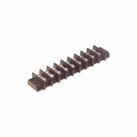
BARRIER BLOCK 9POS .563"
Manufacturer
Cinch Connectors
Series
142r
Type
Wire to Boardr
Specifications of 9-142
Terminal Block Type
Barrier Block
Number Of Circuits
9
Number Of Positions
18
Pitch
0.563" (14.30mm)
Number Of Rows
2
Current
30A
Voltage
250V
Wire Gauge
10 AWG
Mounting Type
Chassis Mount or Panel Mount
Top Termination
Screws
Bottom Termination
Closed
Barrier Type
2 Wall (Dual)
Features
Flange
Color
Black
Operating Temperature
-55°F ~ 300°F
Material - Insulation
Phenol Formaldehyde (Phenolic)
Material Flammability Rating
UL94 V-1
Product
Barrier Terminal Blocks
Number Of Positions / Contacts
9
Current Rating
30 A
Voltage Rating
250 V
Wire Gauge Max (awg)
10
Current, Rating
30 A (Max.)
Length
6.031 in.
Material, Block
Phenolic
Material, Screw
Steel
Mounting Style
Bottom Mounting
Plating, Screw
Nickel over Copper Flash
Screw Size
8-32 x 5⁄16
Temperature Range
-55 to +300 °F
Lead Free Status / RoHS Status
Lead free / RoHS Compliant
Lead Free Status / RoHS Status
Lead free / RoHS Compliant, Lead free / RoHS Compliant
Other names
9-142-P
9142-P
CBB309
9142-P
CBB309
Available stocks
Company
Part Number
Manufacturer
Quantity
Price
Company:

Part Number:
9-1422019-0
Manufacturer:
TE
Quantity:
34 000


D-subminiature Metal Shell
Overmold Kits
D*A and HTD Series
Shield Covers: Steel (stamped) with tin/lead finish
Ferrule: Brass
Call Toll Free: 1 (800) 323-9612
Dimensions
Overmold Shielding Kits
Positions
15 Plug
15 Socket
25 Plug
25 Socket
37 Plug
37 Socket
9 Plug
9 Socket
Cinch overmold kits enable you to overmold the connector of the cable assembly for less
material and process cost (versus a metal backshell), improved appearance, and improved
shielding of the connector to help meet RFI/EMI requirements.
An Overmold Kit catalog number consists of:
-
-
-
You will also need to order the following:
-
-
-
-
All specifications on the connector portion of the overmold kit can be found on pages 4-16 thru
4-17 for HPD 1.5 density and pages 4-20 thru 4-21 for D*A series.
D*A or HTD Crimp and Poke connector.
Inside shielding cover.
Outside shielding cover.
Crimp and Poke stamped contacts must be ordered separately on page 4-22 for D*A
and page 4-18 for HTD connectors.
Ferrules are required, but must be ordered separately according to the size necessary to
accommodate the wire. See page 4-25.
Termination tooling is required to crimp the wires on the connector.
A hand tool and appropriate crimping die are required for crimping the ferrule.
0.270
0.285
0.270
0.285
0.275
0.285
0.275
0.285
in
C
6.86
7.24
6.86
7.24
6.99
7.24
6.99
7.24
mm
0.705 17.91
0.705 17.91
1.050 26.67
1.050 26.67
1.590 40.39
1.590 40.39
2.240 56.90
2.240 56.90
in
D
mm
4-24
1.320 33.53
1.320 33.53
1.320 33.53
1.320 33.53
1.320 33.53
1.320 33.53
1.620 41.15
1.620 41.15
in
E
mm
0.520 13.21
0.520 13.21
0.520 13.21
0.520 13.21
0.520 13.21
0.520 13.21
0.750 19.05
0.750 19.05
in
F
mm
Deg.
75°
75°
58°
58°
40°
40°
32°
32°
G
0.440
0.440
0.440
0.440
0.440
0.440
0.520
0.520
in
H
11.18
11.18
11.18
11.18
11.18
11.18
13.21
13.21
mm
Related parts for 9-142
Image
Part Number
Description
Manufacturer
Datasheet
Request
R

Part Number:
Description:
BARRIER BLOCK 9POS .438"
Manufacturer:
Cinch Connectors
Datasheet:

Part Number:
Description:
BARRIER BLOCK 9POS .375"
Manufacturer:
Cinch Connectors
Datasheet:

Part Number:
Description:
CONN BARRIER BLOCK .375" 9 POS
Manufacturer:
Cinch Connectors
Datasheet:

Part Number:
Description:
CONNECTOR, DSUB FLTR, PLUG, 9POS, 1000PF
Manufacturer:
Cinch Connectors
Datasheet:

Part Number:
Description:
CONNECTOR, DSUB FLTR, RCPT, 9POS, 1000PF
Manufacturer:
Cinch Connectors
Datasheet: