9-142 Cinch Connectors, 9-142 Datasheet - Page 87
9-142
Manufacturer Part Number
9-142
Description
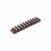
BARRIER BLOCK 9POS .563"
Manufacturer
Cinch Connectors
Series
142r
Type
Wire to Boardr
Specifications of 9-142
Terminal Block Type
Barrier Block
Number Of Circuits
9
Number Of Positions
18
Pitch
0.563" (14.30mm)
Number Of Rows
2
Current
30A
Voltage
250V
Wire Gauge
10 AWG
Mounting Type
Chassis Mount or Panel Mount
Top Termination
Screws
Bottom Termination
Closed
Barrier Type
2 Wall (Dual)
Features
Flange
Color
Black
Operating Temperature
-55°F ~ 300°F
Material - Insulation
Phenol Formaldehyde (Phenolic)
Material Flammability Rating
UL94 V-1
Product
Barrier Terminal Blocks
Number Of Positions / Contacts
9
Current Rating
30 A
Voltage Rating
250 V
Wire Gauge Max (awg)
10
Current, Rating
30 A (Max.)
Length
6.031 in.
Material, Block
Phenolic
Material, Screw
Steel
Mounting Style
Bottom Mounting
Plating, Screw
Nickel over Copper Flash
Screw Size
8-32 x 5⁄16
Temperature Range
-55 to +300 °F
Lead Free Status / RoHS Status
Lead free / RoHS Compliant
Lead Free Status / RoHS Status
Lead free / RoHS Compliant, Lead free / RoHS Compliant
Other names
9-142-P
9142-P
CBB309
9142-P
CBB309
Available stocks
Company
Part Number
Manufacturer
Quantity
Price
Company:

Part Number:
9-1422019-0
Manufacturer:
TE
Quantity:
34 000


CN0942 Series: Fluorosilicone Inserts
T
Designator
*
**
NOTES:
1
CN0944 Series: Neoprene Inserts
Termination Term
Designator Type
*
**
NOTES:
1
CN0942/CN0944 Series (C48 Family)
Short Receptacle Connectors
Non-Removable Contacts
ermination Contact Termination
For other modifications, class, etc., consult factory.
For mounting hole dimensions, see page 3-20.
For other modifications, class, etc., consult factory.
For mounting hole dimensions, see page 3-20.
01*
02*
03**
04**
06*
01*
02*
03**
04**
06*
Applies to CN0944B/CN0944C.
Applies to CN0944D/CN0944E.
Applies to CN0942B/CN0942C.
Applies to CN0942D/CN0942E.
T & W
P & S
X & Y
P & S
Style
X & Y
W
B
C
B
C
T Min. S + .002
T Min. S + .002
.250
.230
.144
.124
.900
.250
.230
.144
.124
.900
Termination
.025
.025
.025
.025
.025
.025
N/A
N/A
N/A
N/A
Ordering Information
Series Designation
Series Modification
B - Square-Flange Mount Bayonet Coupled
C - Square-Flange Mount Thread Coupled
D - Single-Hole Mount Bayonet Coupled
E - Single-Hole Mount Thread Coupled
Shell Size
8, 10, 12, 14, 16, 18, 20, 22, & 24
Class
G - Cadmium/Nickel Finish
J - Anodized Finish
N - Electroless Nickel Finish
Insert Arrangement
(See page 3-4)
Series Designation
CN0944
Series Modification
B - Square-Flange Mount Bayonet Coupled
C - Square-Flange Mount Thread Coupled
D - Single-Hole Mount Bayonet Coupled
E - Single-Hole Mount Thread Coupled
Shell Size
8, 10, 12, 14, 16, 18, 20, 22, & 24
Ordering Information
Environmental Class
G - Cadmium/Nickel Finish
N - Electroless Nickel Finish
R - Anodized Finish
3-10
1
CN0942 B 10 J 05 P N O1
1
CN0944 B 10 R 05 P N C O1
Call Toll Free: 1 (800) 323-9612
Contact Style
• Solder Pin Terminal
P - Pin
S - Socket
• Solder Cup Terminal
X - Pin
Y - Socket
• Wire Wrap Terminal
T - Pin
W - Socket
Termination
(See table)
Shell Position
N, 6, 7, 8, 9, Y (See page 3-4)
Termination
(See table)
Termination Type
B - Solder Pin
C - Solder Cup
W - Wire Wrap
Shell Position
N, 6, 7, 8, 9, Y (See page 3-4)
Contact Style
P - Pin
S - Socket
Insert Arrangement
(See page 3-4)
3
Related parts for 9-142
Image
Part Number
Description
Manufacturer
Datasheet
Request
R

Part Number:
Description:
BARRIER BLOCK 9POS .438"
Manufacturer:
Cinch Connectors
Datasheet:

Part Number:
Description:
BARRIER BLOCK 9POS .375"
Manufacturer:
Cinch Connectors
Datasheet:

Part Number:
Description:
CONN BARRIER BLOCK .375" 9 POS
Manufacturer:
Cinch Connectors
Datasheet:

Part Number:
Description:
CONNECTOR, DSUB FLTR, PLUG, 9POS, 1000PF
Manufacturer:
Cinch Connectors
Datasheet:

Part Number:
Description:
CONNECTOR, DSUB FLTR, RCPT, 9POS, 1000PF
Manufacturer:
Cinch Connectors
Datasheet: