9-142 Cinch Connectors, 9-142 Datasheet - Page 230
9-142
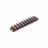
Manufacturer Part Number
9-142
Description
BARRIER BLOCK 9POS .563"
Manufacturer
Cinch Connectors
Series
142r
Type
Wire to Boardr
Specifications of 9-142
Terminal Block Type
Barrier Block
Number Of Circuits
9
Number Of Positions
18
Pitch
0.563" (14.30mm)
Number Of Rows
2
Current
30A
Voltage
250V
Wire Gauge
10 AWG
Mounting Type
Chassis Mount or Panel Mount
Top Termination
Screws
Bottom Termination
Closed
Barrier Type
2 Wall (Dual)
Features
Flange
Color
Black
Operating Temperature
-55°F ~ 300°F
Material - Insulation
Phenol Formaldehyde (Phenolic)
Material Flammability Rating
UL94 V-1
Product
Barrier Terminal Blocks
Number Of Positions / Contacts
9
Current Rating
30 A
Voltage Rating
250 V
Wire Gauge Max (awg)
10
Current, Rating
30 A (Max.)
Length
6.031 in.
Material, Block
Phenolic
Material, Screw
Steel
Mounting Style
Bottom Mounting
Plating, Screw
Nickel over Copper Flash
Screw Size
8-32 x 5⁄16
Temperature Range
-55 to +300 °F
Lead Free Status / RoHS Status
Lead free / RoHS Compliant
Lead Free Status / RoHS Status
Lead free / RoHS Compliant, Lead free / RoHS Compliant
Other names
9-142-P
9142-P
CBB309
9142-P
CBB309
Available stocks
Company
Part Number
Manufacturer
Quantity
Price
Company:

Part Number:
9-1422019-0
Manufacturer:
TE
Quantity:
34 000


Ordering Information
* Assembly in socket connector only.
Dura-Con
High Reliability
Strip Connectors
Dimensions
Socket Connector
Pin Connector
24 Gauge Stainless Steel Guide Pin*
* - Indicates Cinch std. option.
** - Consult factory for larger sizes and multi-row.
Cinch Dura-Con Strip
Thermoplastic
Glass-Reinforced
Strip Connector
Contact Centers
A = .050 (24 Ga.)
Contact Position
1 = Contacts in every position
No. of Contact Positions
1 through 60**
Contact Type
P = Pin
S = Socket
Wire Size in AWG
5 = 25 AWG Solid Copper Wire
6 = 26 AWG Stranded Wire
S = Solder Cup (Skip to
guide pin field if necessary)
CS A 1 10 P 4 C 4-00.5 G
.050" (1.27mm) Density
Solder Cup/Wire
All Plastic
5-39
NOTE:
Dimension A is number
of positions less 1
multiplied by .050
Epoxy
Call Toll Free: 1 (800) 323-9612
Guide Pin (Socket Only)
Empty Cavity (Pin Only)
G02 = Guide Pin Position No. 2
GX = Special Position,
Lead Length in inches
00.5 Solid copper wire only
01.0 Solid copper wire only
02.0 Solid copper wire only
18.0 Stranded wire only
24.0 Stranded wire only
36.0 Stranded wire only
48.0 Stranded wire only
Insulation Color,
Solid Wire Finish,
Solid Cup Finish
*2 = All Yellow
*4 = Gold-Plated (Solid Wire Only)
*5 = Color Coded Per MIL-Std.
Insulation Wire or
Solid Wire Type
C = Solid Copper
E = MIL-W-168 78/4, 7 Strand
1 = All White
3 = Tin-Plated
681, System 1
System 1. (Stranded Wire Only)
Consult Factory
Related parts for 9-142
Image
Part Number
Description
Manufacturer
Datasheet
Request
R

Part Number:
Description:
BARRIER BLOCK 9POS .438"
Manufacturer:
Cinch Connectors
Datasheet:

Part Number:
Description:
BARRIER BLOCK 9POS .375"
Manufacturer:
Cinch Connectors
Datasheet:

Part Number:
Description:
CONN BARRIER BLOCK .375" 9 POS
Manufacturer:
Cinch Connectors
Datasheet:

Part Number:
Description:
CONNECTOR, DSUB FLTR, PLUG, 9POS, 1000PF
Manufacturer:
Cinch Connectors
Datasheet:

Part Number:
Description:
CONNECTOR, DSUB FLTR, RCPT, 9POS, 1000PF
Manufacturer:
Cinch Connectors
Datasheet: