HSDL-3021-021 Lite-On Electronics, HSDL-3021-021 Datasheet - Page 12
HSDL-3021-021
Manufacturer Part Number
HSDL-3021-021
Description
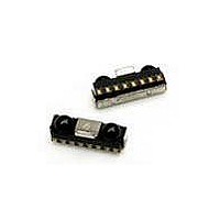
Infrared Transceivers IR Transceiver 4.0Mb/s
Manufacturer
Lite-On Electronics
Datasheet
1.HSDL-3021-021.pdf
(24 pages)
Specifications of HSDL-3021-021
Wavelength
885 nm
Continual Data Transmission
4 Mbit/s
Transmission Distance
50 cm
Radiant Intensity
10 mW/sr
Half Intensity Angle Degrees
30 deg to 60 deg
Pulse Width
4 us, 1.6 us
Maximum Rise Time
40 ns, 600 ns
Maximum Fall Time
40 ns, 600 ns
Led Supply Voltage
0 V to 6.5 V
Operating Voltage
2.4 V to 3.6 V
Maximum Operating Temperature
+ 85 C
Minimum Operating Temperature
- 25 C
Dimensions
8 mm x 3 mm x 2.5 mm
Lead Free Status / RoHS Status
Lead free / RoHS Compliant
Available stocks
Company
Part Number
Manufacturer
Quantity
Price
Company:

Part Number:
HSDL-3021-021
Manufacturer:
Agilent
Quantity:
1
Part Number:
HSDL-3021-021
Manufacturer:
AVAGO/安华高
Quantity:
20 000
Company:
Part Number:
HSDL-3021-021/HSDL3021
Manufacturer:
Agilent
Quantity:
10 000


Recommended Reflow Profile
Process Zone
Heat Up
Solder Paste Dry
Solder Reflow
Cool Down
Time maintained above
liquidus point, 217°C
Peak Temperature
Time within 5°C of actual
Peak Temperature
Time 25°C to Peak Temperature
The reflow profile is a straight-line representation of a
nominal temperature profile for a convective reflow sol-
der process. The temperature profile is divided into four
process zones, each with different DT/Dtime tempera-
ture change rates, or duration. The DT/Dtime rates, or du-
ration, are detailed in the above table. The temperatures
are measured at the component to printed circuit board
connections.
In process zone P1, the PC board and HSDL-3021 pins are
heated to a temperature of 150°C to activate the flux in
the solder paste. The temperature ramp up rate, R1, is
limited to 3°C per second to allow for even heating of
both the PC board and HSDL-3021 pins.
Process zone P2 should be of sufficient time duration (100
to 180 seconds) to dry the solder paste. The temperature
is raised to a level just below the liquidus point of the
solder.
12
255
230
217
200
180
150
120
80
25
0
HEAT
R1
UP
P1
50
SOLDER PASTE DRY
R2
100
Symbol
P1, R1
P2, R2
P3, R3
P3, R4
P4, R5
P2
t-TIME (SECONDS)
150
R3
60 sec.to 90 sec.
MAX. 260°C
REFLOW
SOLDER
ABOVE
200
217°C
P3
R4
DT
25°C to 150°C
150°C to 200°C
200°C to 260°C
260°C to 200°C
200°C to 25°C
>217°C
260°C
–
25°C to 260°C
Process zone P3 is the solder reflow zone. In zone P3, the
temperature is quickly raised above the liquidus point
of solder to 260°C (500°F) for optimum results. The dwell
time above the liquidus point of solder should be be-
tween 60 and 90 seconds. This is to assure proper co-
alescing of the solder paste into liquid solder and the
formation of good solder connections. Beyond the rec-
ommended dwell time, the intermetallic growth within
the solder connections becomes excessive, resulting in
the formation of weak and unreliable connections. The
temperature is then rapidly reduced to a point below
the solidus temperature of the solder to allow the solder
within the connections to freeze solid.
Process zone P4 is the cool down after solder freeze. The
cool down rate, R5, from the liquidus point of the solder
to 25°C (77°F) should not exceed 6°C per second maxi-
mum. This limitation is necessary to allow the PC board
and HSDL-3021 pins to change dimensions evenly, put-
ting minimal stresses on the HSDL-3021.
It is recommended to perform reflow soldering no more
than twice.
DOWN
250
COOL
P4
R5
300
Maximum DT/DTime or Duration
3°C/s
100s to 180s
3°C/s
-6°C/s
-6°C/s
60s to 90s
–
20s to 40s
8 mins
Related parts for HSDL-3021-021
Image
Part Number
Description
Manufacturer
Datasheet
Request
R

Part Number:
Description:
EMITTER IR 5MM 875NM
Manufacturer:
Lite-On Electronics
Datasheet:

Part Number:
Description:
Infrared Transceivers IR Transceiver 115.2Kb/s
Manufacturer:
Lite-On Electronics
Datasheet:

Part Number:
Description:
EMITTER IR 5MM HI POWER 870NM
Manufacturer:
Lite-On Electronics
Part Number:
Description:
Infrared Transceivers IR Transceiver 115.2Kb/s
Manufacturer:
Lite-On Electronics
Datasheet:
Part Number:
Description:
Infrared Transceivers IR Transceiver 115.2Kb/s
Manufacturer:
Lite-On Electronics
Datasheet:

Part Number:
Description:
Infrared Transceivers IR Transceiver 115Kb/s
Manufacturer:
Lite-On Electronics
Datasheet:
Part Number:
Description:
Infrared Transceivers IR Transceiver 115.2Kb/s
Manufacturer:
Lite-On Electronics

Part Number:
Description:
Infrared Transceivers IR Transceiver
Manufacturer:
Lite-On Electronics
Datasheet:
Part Number:
Description:
IRDA TX/RX 0.1152Mbps 3.3V 8-Pin Ultra Small Profile T/R
Manufacturer:
Lite-On Electronics
Datasheet:
Part Number:
Description:
IRDA TX/RX 0.1152Mbps 3.3V 8-Pin T/R
Manufacturer:
Lite-On Electronics
Datasheet:
Part Number:
Description:
ENCODER/DECODER 3/16 8-SOIC
Manufacturer:
Lite-On Electronics
Datasheet:

Part Number:
Description:
OPTOCOUPLER HS LOGIC OUT 8-DIP
Manufacturer:
Lite-On Electronics
Datasheet:

Part Number:
Description:
OPTOCOUPLER HS TRANS OUT 8-DIP
Manufacturer:
Lite-On Electronics
Datasheet:

Part Number:
Description:
OPTOCOUPLER HS TRANS OUT 8-SMD
Manufacturer:
Lite-On Electronics
Datasheet:

Part Number:
Description:
OPTOCOUPLER HS TRANS OUT 8-DIP
Manufacturer:
Lite-On Electronics
Datasheet: