HSDL-3021-021 Lite-On Electronics, HSDL-3021-021 Datasheet - Page 3
HSDL-3021-021
Manufacturer Part Number
HSDL-3021-021
Description
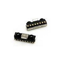
Infrared Transceivers IR Transceiver 4.0Mb/s
Manufacturer
Lite-On Electronics
Datasheet
1.HSDL-3021-021.pdf
(24 pages)
Specifications of HSDL-3021-021
Wavelength
885 nm
Continual Data Transmission
4 Mbit/s
Transmission Distance
50 cm
Radiant Intensity
10 mW/sr
Half Intensity Angle Degrees
30 deg to 60 deg
Pulse Width
4 us, 1.6 us
Maximum Rise Time
40 ns, 600 ns
Maximum Fall Time
40 ns, 600 ns
Led Supply Voltage
0 V to 6.5 V
Operating Voltage
2.4 V to 3.6 V
Maximum Operating Temperature
+ 85 C
Minimum Operating Temperature
- 25 C
Dimensions
8 mm x 3 mm x 2.5 mm
Lead Free Status / RoHS Status
Lead free / RoHS Compliant
Available stocks
Company
Part Number
Manufacturer
Quantity
Price
Company:

Part Number:
HSDL-3021-021
Manufacturer:
Agilent
Quantity:
1
Part Number:
HSDL-3021-021
Manufacturer:
AVAGO/安华高
Quantity:
20 000
Company:
Part Number:
HSDL-3021-021/HSDL3021
Manufacturer:
Agilent
Quantity:
10 000


I/O Pins Configuration Table
Pin
1
2
3
4
5
6
7
8
–
Notes:
1. Tied through external resistor, R2, to Vled. Refer to the table below for recommended series resistor value.
2. Connect to ASIC logic controller supply voltage or V
3. This pin is used to transmit serial data when SD pin is low. If held high for longer than 50 µs, the LED is turned off. Do NOT float this pin.
4. This pin is capable of driving a standard CMOS or TTL load. No external pull-up or pull-down resistor is required. The pin is in tri-state when the
5. Complete shutdown of IC and PIN diode. The pin is used for setting IR receiver bandwidth, range of IR LED current and RC drive programming
6. Regulated, 2.4 V to 3.6 V.
7. Logic high turns on the RC LED. If held high longer than 50 µs, the RC LED is turned off. Do NOT float the pin.
8. Connect to system ground.
9. Connect to system ground via a low inductance trace. For best performance, do not connect directly to the transceiver GND pin.
Recommended Application Circuit Components
Component
R1
R2
CX1, CX3, CX5
CX2, CX4
Note:
1. CX1, CX2, CX3 & CX4 must be placed within 0.7 cm of HSDL-3021 to obtain optimum noise
immunity.
3
transceiver is in shutdown mode.
mode. Refer to section on “Bandwidth Selection Timing” and “Remote Control Drive Modes” for more information. Do NOT float this pin. ***
CAUTIONS: The BiCMOS inherent to the design of this component increases the component’s susceptibility to damage
from electrostatic discharge (ESD). It is advised that normal static precautions be taken in handling and assembly of
this component to prevent damage and/or degradation which may be induced by ESD.
Symbol
LEDA
IOV
TxD_IR
RxD
SD
V
TxD_RC
GND
Shield
CC
CC
Recommended Value
4.7 Ω, ± 5%, 0.25 watt
2.7 Ω, for 2.4 < VLED ≤ 2.7 V;
3.3 Ω, for 2.7 < VLED ≤ 3.0 V
3.9 Ω, for 3.0 < VLED ≤ 3.3 V
4.7 Ω, for 3.3 < VLED ≤ 3.6 V
5.6 Ω, for 3.6 < VLED ≤ 4.2 V
10 Ω, for 4.2 < VLED ≤ 5 V
100 nF, ± 20%, X7R Ceramic
4.7 µF, ± 20%, Tantalum
Description
LED Anode
Input/Output ASIC Voltage
IrDA Transmitter Data Input
IrDA Receive Data
Shutdown
Supply Voltage
RC Transmitter Data Input
Ground
EMI shield
CC
. The voltage at this pin should be equal to or less than V
Note
1
1
I/O Type
Input. Active High
Output. Active Low
Input. Active High
Input. Active High
CC
.
Notes
Note 1
Note 2
Note 3
Note 4
Note 5
Note 6
Note 7
Note 8
Note 9
Related parts for HSDL-3021-021
Image
Part Number
Description
Manufacturer
Datasheet
Request
R

Part Number:
Description:
EMITTER IR 5MM 875NM
Manufacturer:
Lite-On Electronics
Datasheet:

Part Number:
Description:
Infrared Transceivers IR Transceiver 115.2Kb/s
Manufacturer:
Lite-On Electronics
Datasheet:

Part Number:
Description:
EMITTER IR 5MM HI POWER 870NM
Manufacturer:
Lite-On Electronics
Part Number:
Description:
Infrared Transceivers IR Transceiver 115.2Kb/s
Manufacturer:
Lite-On Electronics
Datasheet:
Part Number:
Description:
Infrared Transceivers IR Transceiver 115.2Kb/s
Manufacturer:
Lite-On Electronics
Datasheet:

Part Number:
Description:
Infrared Transceivers IR Transceiver 115Kb/s
Manufacturer:
Lite-On Electronics
Datasheet:
Part Number:
Description:
Infrared Transceivers IR Transceiver 115.2Kb/s
Manufacturer:
Lite-On Electronics

Part Number:
Description:
Infrared Transceivers IR Transceiver
Manufacturer:
Lite-On Electronics
Datasheet:
Part Number:
Description:
IRDA TX/RX 0.1152Mbps 3.3V 8-Pin Ultra Small Profile T/R
Manufacturer:
Lite-On Electronics
Datasheet:
Part Number:
Description:
IRDA TX/RX 0.1152Mbps 3.3V 8-Pin T/R
Manufacturer:
Lite-On Electronics
Datasheet:
Part Number:
Description:
ENCODER/DECODER 3/16 8-SOIC
Manufacturer:
Lite-On Electronics
Datasheet:

Part Number:
Description:
OPTOCOUPLER HS LOGIC OUT 8-DIP
Manufacturer:
Lite-On Electronics
Datasheet:

Part Number:
Description:
OPTOCOUPLER HS TRANS OUT 8-DIP
Manufacturer:
Lite-On Electronics
Datasheet:

Part Number:
Description:
OPTOCOUPLER HS TRANS OUT 8-SMD
Manufacturer:
Lite-On Electronics
Datasheet:

Part Number:
Description:
OPTOCOUPLER HS TRANS OUT 8-DIP
Manufacturer:
Lite-On Electronics
Datasheet: