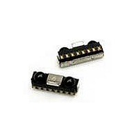
HSDL-3021-021 Lite-On Electronics, HSDL-3021-021 Datasheet - Page 6

HSDL-3021-021
Manufacturer Part Number
HSDL-3021-021
Description
Infrared Transceivers IR Transceiver 4.0Mb/s
Manufacturer
Lite-On Electronics
Datasheet
1.HSDL-3021-021.pdf
(24 pages)
Specifications of HSDL-3021-021
Wavelength
885 nm
Continual Data Transmission
4 Mbit/s
Transmission Distance
50 cm
Radiant Intensity
10 mW/sr
Half Intensity Angle Degrees
30 deg to 60 deg
Pulse Width
4 us, 1.6 us
Maximum Rise Time
40 ns, 600 ns
Maximum Fall Time
40 ns, 600 ns
Led Supply Voltage
0 V to 6.5 V
Operating Voltage
2.4 V to 3.6 V
Maximum Operating Temperature
+ 85 C
Minimum Operating Temperature
- 25 C
Dimensions
8 mm x 3 mm x 2.5 mm
Lead Free Status / RoHS Status
Lead free / RoHS Compliant
Available stocks
Company
Part Number
Manufacturer
Quantity
Price
Company:
Part Number:
HSDL-3021-021
Manufacturer:
Agilent
Quantity:
1
Part Number:
HSDL-3021-021
Manufacturer:
AVAGO/安华高
Quantity:
20 000
Company:
Part Number:
HSDL-3021-021/HSDL3021
Manufacturer:
Agilent
Quantity:
10 000
Electrical and Optical Specifications (Cont’d.)
Parameter
IR LED Anode On-State Voltage
(SIR Mode)
IR LED Anode On-State Voltage
(MIR/FIR Mode)
Remote Control (RC) Transmitter
RC Radiant Intensity
RC Viewing Angle
RC Peak Wavelength
TxD_RC Logic Levels
TxD_RC Input Current
RC LED Anode On-State Voltage
Transceiver
Input Current
Supply Current
Notes:
4. An in-band optical signal is a pulse/sequence where the peak wavelength, l
5. For in-band signals 115.2 kbit/s where 9 µW/cm
6. For in-band signals 1.152 Mbit/s where 22 µW/cm
7. For in-band signals 4 Mbit/s where 22 µW/cm
8. Latency is defined as the time from the last TxD_IrDA light output pulse until the receiver has recovered full sensitivity.
9. Receiver Wake Up Time is measured from V
10, Transmitter Wake Up Time is measured from V
11. The Max Optical PW is defined as the maximum time which the IR LED will turn on. This is to prevent the long Turn On time for the IR LED.
6
tics are compliant with the IrDA Serial Infrared Physical Layer Link Specification version 1.4.
High
Low
High
Low
High
Low
Shutdown I
Idle
(Standby)
Active
Symbol
V
(IR_LEDA)
V
(IR_LEDA)
I
2q
l
V
V
I
I
V
(RC_LEDA)
I
I
I
I
EH
H
L
H
L
CC1
CC2
CC3
ON
ON
P
IH
IL
ON
CC
1/2
power ON to valid RxD_IrDA output.
2
CC
≤ EI ≤ 500 mW/cm
2
power ON to valid light output in response to a TxD_IrDA pulse.
≤ EI ≤ 500 mW/cm
2
≤ EI ≤ 500 mW/cm
Min.
30
IOV
0
-1
CC
- 0.5
2
.
2
.
2
Typ.
2.19
2.22
50
885
0.02
-0.02
2.08
0.01
-0.02
2.0
3.5
.
P
, is defined as 850 nm ≤ l
Max.
60
IOV
0.5
1
1
1
1
1
2.9
CC
Units
V
V
mW/sr
°
nm
V
V
µA
µA
V
µA
µA
µA
mA
mA
P
≤ 900 nm, and the pulse characteris-
Conditions
IR_I
IR VLED = 3.6 V, R = 13 Ω,
V
IR_I
IR VLED = 3.6 V, R = 13 Ω,
V
RC_I
q
T
V
0 ≤ V
RC_I
RC VLED = 3.6 V, R = 3.9 Ω,
V
V
0 ≤ V
V
V
V
A
I
I
1/2
I
I
I
SD
I(TxD)
I(TxD)
(TxD_IR) ≥ V
(TxD_RC) ≥ V
≥ V
(TxD) ≥ V
= 25°C
≥ V
≥ V
LEDA
LEDA
≤ 15°, TxD_RC ≥ V
LEDA
LEDA
I
I
IH
≤ V
IH
≤ V
≤ V
≥ V
CC
= 65 mA,
= 150 mA,
= 250 mA,
IL
IL
= 250 mA,
IL
IL
- 0.5, T
, EI = 0
, EI = 10 mW/cm
IH
IH
IH
A
= 25°C
IH
,
2


