EVALA5973AD STMicroelectronics, EVALA5973AD Datasheet - Page 6
EVALA5973AD
Manufacturer Part Number
EVALA5973AD
Description
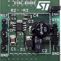
Power Management Modules & Development Tools EVAL BOARD A5973AD Auto Grade
Manufacturer
STMicroelectronics
Type
DC/DC Switching Converters, Regulators & Controllersr
Datasheet
1.EVALA5973D.pdf
(30 pages)
Specifications of EVALA5973AD
Input Voltage
4.4 V to 36 V
Output Voltage
1.235 V to 35 V
Board Size
23 mm x 20 mm
Product
Power Management Modules
Supply Current
2.5 A
Dimensions
23 mm x 20 mm
For Use With/related Products
AN1518
Lead Free Status / RoHS Status
Lead free / RoHS Compliant


Functional description
3
3.1
3.2
6/30
Functional description
The main internal blocks are shown in the device block diagram in
●
●
●
●
●
●
●
●
●
Power supply & voltage reference
The internal regulator circuit (shown in
voltage Preregulator, the Bandgap voltage reference and the Bias block that provides
current to all the blocks. The Starter supplies the start-up currents to the entire device when
the input voltage goes high and the device is enabled (inhibit pin connected to ground). The
Preregulator block supplies the Bandgap cell with a preregulated voltage V
very low supply voltage noise sensitivity.
Voltages monitor
An internal block continuously senses the V
their thresholds, the regulator begins operating. There is also a hysteresis on the V
(UVLO).
Figure 5.
A voltage regulator supplying the internal circuitry. From this regulator, a 3.3 V
reference voltage is externally available.
A voltage monitor circuit which checks the input and the internal voltages.
A fully integrated sawtooth oscillator with a frequency of 250 kHz ±15%, including also
the voltage feed forward function and an input/output synchronization pin.
Two embedded current limitation circuits which control the current that flows through
the power switch. The pulse-by-pulse current limit forces the power switch OFF cycle
by cycle if the current reaches an internal threshold, while the frequency shifter reduces
the switching frequency in order to significantly reduce the duty cycle.
A transconductance error amplifier.
A pulse width modulator (PWM) comparator and the relative logic circuitry necessary to
drive the internal power.
A high side driver for the internal P-MOS switch.
An inhibit block for stand-by operation.
A circuit to implement the thermal protection function.
Internal circuit
Figure
cc
, V
5) consists of a start-up circuit, an internal
ref
and V
bg
. If the voltages go higher than
Figure
4. They are:
REG
that has a
CC
AN1518
Related parts for EVALA5973AD
Image
Part Number
Description
Manufacturer
Datasheet
Request
R

Part Number:
Description:
ENERCHIP CC EVAL KIT
Manufacturer:
Cymbet Corporation
Datasheet:

Part Number:
Description:
BOARD EVAL FOR AD976
Manufacturer:
Analog Devices Inc
Datasheet:

Part Number:
Description:
BOARD EVAL FOR ADXL345
Manufacturer:
Analog Devices Inc
Datasheet:

Part Number:
Description:
ENERCHIP CC SEH EVAL KIT
Manufacturer:
Cymbet Corporation
Datasheet:

Part Number:
Description:
ENERCHIP EP ENERGY HARVEST EVAL
Manufacturer:
Cymbet Corporation
Datasheet:

Part Number:
Description:
EVAL BOARD FOR TW6864-LB2-GR
Manufacturer:
Intersil
Datasheet:
Part Number:
Description:
EVAL BOARD FOR TW8816-LB3-GR
Manufacturer:
Intersil
Datasheet:
Part Number:
Description:
EVAL BOARD FOR TW8817-TA3-GRS
Manufacturer:
Intersil
Datasheet:

Part Number:
Description:
EVALUATION MODULE FOR ADUM4160
Manufacturer:
Analog Devices Inc
Datasheet:

Part Number:
Description:
BOARD EVALUATION ADCMP581BCP
Manufacturer:
Analog Devices Inc
Datasheet:
Part Number:
Description:
BOARD EVALUATION ADM1041
Manufacturer:
Analog Devices Inc
Datasheet:

Part Number:
Description:
EVAL BOARD FOR STM32F107VCT
Manufacturer:
STMicroelectronics
Datasheet:
Part Number:
Description:
BOARD EVAL FOR AD1954
Manufacturer:
Analog Devices Inc
Datasheet:
Part Number:
Description:
BOARD EVAL FOR AD1955
Manufacturer:
Analog Devices Inc
Datasheet:

Part Number:
Description:
BOARD EVAL FOR AD7655
Manufacturer:
Analog Devices Inc
Datasheet: