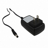
VNCLO-PSU-USA FTDI, Future Technology Devices International Ltd, VNCLO-PSU-USA Datasheet - Page 8

VNCLO-PSU-USA
Manufacturer Part Number
VNCLO-PSU-USA
Description
POWER SUPPLY FOR VNCLO-MB1A USA
Manufacturer
FTDI, Future Technology Devices International Ltd
Series
Vinculor
Specifications of VNCLO-PSU-USA
Accessory Type
Power Supply
Lead Free Status / RoHS Status
Lead free / RoHS Compliant
For Use With/related Products
FTDI Vinculo Boards
Other names
768-1092
4
The Vinculum II IDE is used to create application code to run on VNC2. This section gives some example
source code, and explains its operation, used to drive the LCD display via the Vinco module.
Note the full project can be downloaded at:
http://www.ftdichip.com/Support/SoftwareExamples/VinculumIIProjects/Vinco_LCD.zip
4.1 VNC2 Initialisation
When generating firmware for VNC2, the first steps are to enable the Vinculum Operating System (VOS),
which controls the VNC2 services and device manager, defines the clock speed the core will use, and
defines the VNC2 pins that will be used. This is done in the function labelled main. The “main” function
for this application is shown as follows
Void main (void)
{
// GPIO context structure
// call VOS initialisation routines
The main function will also initialise the device drivers used in this application (GPIO in this case), it then
defines the threads that will be started (labelled firmware in this project) and finally it starts the VOS
scheduler. This is shown as follows:
// initialise device drivers
// TODO: call initialisation routines for included device drivers
Source code for the VNC2 writing to LCD Display
gpio_context_t gpioCtx;
vos_init(10, VOS_TICK_INTERVAL, NUMBER_OF_DEVICES);
vos_set_clock_frequency(VOS_48MHZ_CLOCK_FREQUENCY);
if
{
gpioCtx.port_identifier = GPIO_PORT_A;
gpio_init(VOS_DEV_GPIO,&gpioCtx);
// create threads for firmware application (no parameters)
tcbFirmware = vos_create_thread(29, SIZEOF_THREAD_MEMORY, firmware, 0);
// start VOS scheduler
vos_start_scheduler();
(vos_get_package_type() == VINCULUM_II_64_PIN)
// GPIO port A bit 0 to pin 51
vos_iomux_define_output(51,IOMUX_OUT_GPIO_PORT_A_0);
// GPIO port A bit 1 to pin 52
vos_iomux_define_output(52,IOMUX_OUT_GPIO_PORT_A_1);
// GPIO port A bit 2 to pin 55
vos_iomux_define_output(55,IOMUX_OUT_GPIO_PORT_A_2);
// GPIO port A bit 3 to pin 56
vos_iomux_define_output(56,IOMUX_OUT_GPIO_PORT_A_3);
// GPIO port A bit 4 to pin 57
vos_iomux_define_output(57,IOMUX_OUT_GPIO_PORT_A_4);
// GPIO port A bit 5 to pin 58
vos_iomux_define_output(58,IOMUX_OUT_GPIO_PORT_A_5);
// UART to V2EVAL board pins
Copyright © 2010 Future Technology Devices International Limited
`
AN_153 Vinco LCD Interface Example
Document Reference No.: FT_000332
// DB4
// DB5
// DB6
// DB7
// RS
// E
Clearance No.: FTDI# 177
Version
7
2.0


