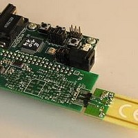
MC33696MOD868EV Freescale Semiconductor, MC33696MOD868EV Datasheet - Page 29

MC33696MOD868EV
Manufacturer Part Number
MC33696MOD868EV
Description
MCU, MPU & DSP Development Tools MC33696 (ECHO) RF C EVAL
Manufacturer
Freescale Semiconductor
Datasheet
1.MC33696MOD868EV.pdf
(80 pages)
Specifications of MC33696MOD868EV
Processor To Be Evaluated
MC9S08RG60
Interface Type
RS-232
Lead Free Status / RoHS Status
Lead free / RoHS Compliant
- Current page: 29 of 80
- Download datasheet (2Mb)
15.2 State Machine
The configuration mode is selected by the microcontroller unit (MCU) to write to the internal registers (to
configure the system) or to read them. In this mode, the SPI is a slave. The analog parts (receiver and
transmitter) remain in the state (on, off) they were in prior to entering configuration mode, until a new
configuration changes them. In configuration mode, data can be neither sent nor received. As long as a low
level is applied to CONFB, the circuit stays in State 1, the only state in this mode.
Figure 22
configuration mode. SPI startup time corresponds to the addition of the crystal oscillator lock time
(parameter 5.10) and the PLL lock time (parameter 5.9).
Freescale Semiconductor
STROBE
STROBE
STROBE
(Output)
(Output)
CONFB
CONFB
CONFB
(Output)
(Input)
(Input)
(Input)
(Input)
SCLK
SCLK
(Input)
MOSI
MOSI
MISO
MISO
(Input)
SCLK
MOSI
MISO
SEB
SEB
SEB
1
1
0
0
1
1
0
0
1
1
0
0
1
1
0
0
1
1
0
0
1
1
0
0
1
0
1
0
1
0
1
0
1
0
1
0
describe the valid sequence for enabling a correct transition from Standby/LVD mode to
N1 N0 A4 A3 A2 A1 A0 R/W
N1 N0 A4 A3 A2 A1 A0 R/W
N1 N0 A4 A3 A2 A1 A0 R/W
Figure 20. Write Operation in Configuration Mode (N[1:0] = 01)
Figure 21. Read Operation in Configuration Mode (N[1:0] = 01)
MC33696 Data Sheet, Rev. 12
D7 D6 D5 D4 D3 D2 D1 D0
D7 D6 D5 D4 D3 D2 D1 D0
D7 D6 D5 D4 D3 D2 D1
D0
D7 D6 D5 D4 D3 D2 D1 D0
D7 D6 D5 D4 D3 D2 D1 D0
D7 D6 D5 D4 D3 D2 D1 D0
Configuration Mode
29
Related parts for MC33696MOD868EV
Image
Part Number
Description
Manufacturer
Datasheet
Request
R
Part Number:
Description:
Manufacturer:
Freescale Semiconductor, Inc
Datasheet:
Part Number:
Description:
Manufacturer:
Freescale Semiconductor, Inc
Datasheet:
Part Number:
Description:
Manufacturer:
Freescale Semiconductor, Inc
Datasheet:
Part Number:
Description:
Manufacturer:
Freescale Semiconductor, Inc
Datasheet:
Part Number:
Description:
Manufacturer:
Freescale Semiconductor, Inc
Datasheet:
Part Number:
Description:
Manufacturer:
Freescale Semiconductor, Inc
Datasheet:
Part Number:
Description:
Manufacturer:
Freescale Semiconductor, Inc
Datasheet:
Part Number:
Description:
Manufacturer:
Freescale Semiconductor, Inc
Datasheet:
Part Number:
Description:
Manufacturer:
Freescale Semiconductor, Inc
Datasheet:
Part Number:
Description:
Manufacturer:
Freescale Semiconductor, Inc
Datasheet:
Part Number:
Description:
Manufacturer:
Freescale Semiconductor, Inc
Datasheet:
Part Number:
Description:
Manufacturer:
Freescale Semiconductor, Inc
Datasheet:
Part Number:
Description:
Manufacturer:
Freescale Semiconductor, Inc
Datasheet:
Part Number:
Description:
Manufacturer:
Freescale Semiconductor, Inc
Datasheet:
Part Number:
Description:
Manufacturer:
Freescale Semiconductor, Inc
Datasheet:


