GA200SA60UP Vishay, GA200SA60UP Datasheet

IGBT Transistors N-Ch 600 Volt 100A

GA200SA60UP

Manufacturer Part Number
GA200SA60UP
Description
IGBT Transistors N-Ch 600 Volt 100A
Manufacturer
Vishay
Datasheet

Specifications of GA200SA60UP

Configuration
Single
Collector- Emitter Voltage Vceo Max
600 V
Maximum Gate Emitter Voltage
+/- 20 V
Maximum Operating Temperature
+ 150 C
Package / Case
SOT-227-4
Continuous Collector Current Ic Max
200 A
Minimum Operating Temperature
- 55 C
Mounting Style
SMD/SMT
Dc Collector Current
200A
Collector Emitter Voltage Vces
600V
Power Dissipation Pd
500W
Collector Emitter Voltage V(br)ceo
600V
Operating Temperature Range
-55°C To +150°C
No. Of Pins
4
Lead Free Status / RoHS Status
Lead free / RoHS Compliant
Lead Free Status / RoHS Status
Lead free / RoHS Compliant, Lead free / RoHS Compliant

Available stocks

Company
Part Number
Manufacturer
Quantity
Price
Part Number:
GA200SA60UP
Quantity:
63
Part Number:
GA200SA60UPBF
Manufacturer:
AVX
Quantity:
25 000
Document Number: 94364
Revision: 22-Jul-10
PRODUCT SUMMARY
ABSOLUTE MAXIMUM RATINGS
PARAMETER
Collector to emitter breakdown voltage
Continuous collector current
Pulsed collector current
Clamped inductive load current
Gate to emitter voltage
Reverse voltage avalanche energy
RMS isolation voltage
Maximum power dissipation
Operating junction and storage
temperature range
Mounting torque
THERMAL AND MECHANICAL SPECIFICATIONS
PARAMETER
Junction to case
Case to sink, flat, greased surface
Weight of module
V
CE(on)
V
V
CES
I
GE
(typical)
C
SOT-227
DiodesAmericas@vishay.com, DiodesAsia@vishay.com,
For technical questions within your region, please contact one of the following:
Insulated Gate Bipolar Transistor
(Ultrafast Speed IGBT), 100 A
1.92 V
600 V
100 A
15 V
SYMBOL
SYMBOL
T
R
R
V
V
E
J
V
I
I
, T
P
thJC
thCS
ISOL
CES
CM
ARV
I
LM
GE
C
D
Stg
T
T
V
L = 10 μH, R
See fig. 13a
Repetitive rating; pulse width limited
by maximum junction temperature
Any terminal to case, t = 1 minute
T
T
6-32 or M3 screw
C
C
CC
C
C
= 25 °C
= 100 °C
= 25 °C
= 100 °C
= 80 % (V
TEST CONDITIONS
FEATURES
• Ultrafast: Optimized for minimum saturation
• Very low conduction and switching losses
• Fully isolate package (2500 V
• Very low internal inductance ( 5 nH typical)
• Industry standard outline
• UL approved file E78996
• Compliant to RoHS directive 2002/95/EC
• Designed and qualified for industrial level
BENEFITS
• Designed for increased operating efficiency in power
• Lower overall losses available at frequencies = 20 kHz
• Easy to assemble and parallel
• Direct mounting to heatsink
• Lower EMI, requires less snubbing
• Plug-in compatible with other SOT-227 packages
TYP.
0.05
voltage and speed up to 40 kHz in hard
switching, > 200 kHz in resonant mode
conversion: UPS, SMPS, welding, induction heating
30
G
-
CES
= 2.0 ,
), V
DiodesEurope@vishay.com
GE
= 20 V,
Vishay Semiconductors
MAX.
- 55 to + 150
0.25
-
-
AC/RMS
1.3 (12)
GA200SA60UP
MAX.
2500
± 20
600
200
100
400
400
160
500
200
)
www.vishay.com
(lbf in)
UNITS
UNITS
N  m
°C/W
mJ
°C
W
V
A
V
V
g
1

Related parts for GA200SA60UP

GA200SA60UP Summary of contents

Page 1

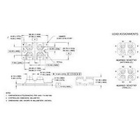
... Any terminal to case minute ISOL ° 100 ° Stg 6- screw SYMBOL TYP thJC R 0.05 thCS 30 DiodesEurope@vishay.com GA200SA60UP Vishay Semiconductors ) AC/RMS MAX. UNITS 600 200 100 400 = 20 V, 400 ± 20 160 2500 500 200 - 150 1.3 (12) (lbf in) MAX. UNITS 0. www.vishay.com ...

Page 2

... GA200SA60UP Vishay Semiconductors ELECTRICAL SPECIFICATIONS (T PARAMETER Collector to emitter breakdown voltage Emitter to collector breakdown voltage Temperature coeff. of breakdown Collector to emitter saturation voltage Gate threshold voltage Temperature coeff. of threshold voltage Forward transconductance Zero gate voltage collector current Gate to emitter leakage current SWITCHING CHARACTERISTICS (T ...

Page 3

... Fig Typical Load Current vs. Frequency (Load Current = I of Fundamental) RMS µs pulse width 2.5 3.0 3 µs pulse width 7.0 8.0 GA200SA60UP Vishay Semiconductors For both: Duty cycle 125 ° °C sink Gate drive as specified Power dissipation = 140 W 10 100 200 150 100 ...

Page 4

... GA200SA60UP Vishay Semiconductors 0. 0.02 0. 0.01 0.001 0.00001 Fig Maximum Effektive Transient Thermal Impedance, Junction to Case 30 000 MHz ies ge 25 000 res oes ce 20 000 C ies 15 000 C oes 10 000 5000 C res Collector to Emitter Voltage (V) CE Fig Typical Capacitance vs. ...

Page 5

... Note: Due to the 50 V power supply, pulse width and inductor 300 400 480 100 1000 d(off d(on Fig. 14b - Switching Loss Waveforms GA200SA60UP Vishay Semiconductors 1000 (max will increase to obtain rated I d Fig. 13a - Clamped Inductive Load Test Circuit 480 µF 960 V Fig. 13b - Pulsed Collector Current Test Circuit L Driver* V ...

Page 6

... GA200SA60UP Vishay Semiconductors ORDERING INFORMATION TABLE Device code CIRCUIT CONFIGURATION 2 (G) Dimensions Packaging information www.vishay.com For technical questions within your region, please contact one of the following: 6 DiodesAmericas@vishay.com, DiodesAsia@vishay.com, Insulated Gate Bipolar Transistor (Ultrafast Speed IGBT), 100 A A 200 Insulated Gate Bipolar Transistor (IGBT) ...

Page 7

... Vishay product could result in personal injury or death. Customers using or selling Vishay products not expressly indicated for use in such applications their own risk and agree to fully indemnify and hold Vishay and its distributors harmless from and against any and all claims, liabilities, expenses and damages arising or resulting in connection with such use or sale, including attorneys fees, even if such claim alleges that Vishay or its distributor was negligent regarding the design or manufacture of the part ...

Related keywords