AC164142 Microchip Technology, AC164142 Datasheet - Page 25
AC164142
Manufacturer Part Number
AC164142
Description
Consumer-band BPSK 7.2kbps PLM PICtail Plus Daughter Board Other
Manufacturer
Microchip Technology
Series
PICtail™ Plusr
Specifications of AC164142
Kit Application Type
Communication
Silicon Family Name
DsPIC
Kit Contents
2x Power-Line Soft-Modem PICtail Plus Daughter Boards, 2x High Voltage Adapter Cables, Info Sheet
Features
Operates On 5V And 9V
Rohs Compliant
Yes
Processor To Be Evaluated
dsPIC33F
Processor Series
dsPIC33F
Operating Supply Voltage
5 V, 9 V
Featured Product
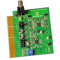
AC164142 PICtail⢠Plus Daughter Board
Main Purpose
Interface, Power Line Transceiver
Embedded
No
Utilized Ic / Part
-
Primary Attributes
AC Power Line Transceiver, BPSK 7.2 Kbps
Secondary Attributes
Requires Explorer 16 Boards
Lead Free Status / Rohs Status
Lead free / RoHS Compliant
Available stocks
Company
Part Number
Manufacturer
Quantity
Price
Company:

Part Number:
AC164142
Manufacturer:
MICROCHIP
Quantity:
12 000
Part Number:
AC164142
Manufacturer:
BOARD
Quantity:
20 000


3.2
© 2011 Microchip Technology Inc.
DEMONSTRATION APPLICATIONS
The five demonstration applications developed for the daughter board are described in
this section. Peripherals on the Explorer 16 Development Board, such as the LCD
screen, push buttons and LEDs, are used by the demonstration applications to interact
with the user. In general, LED D3 indicates the transmission status, LED D5 indicates
the receiver bit synchronization status, and LED D4 indicates the receiver byte
synchronization status.
Table 3-2
applications. The listed memory requirements are valid only when the default
configuration settings are used (source codes provided on the web site are configured
with default configuration settings). Changing the configuration settings may cause
significant changes in the memory requirements.
TABLE 3-2:
3.2.1
This demonstration evaluates the two-way power line communication link between two
development boards.
1. Program two Explorer 16 Development Boards with the same demonstration
2. Connect the development boards to a power line and power up the Explorer 16
3. Press the S5 button on one of the Explorer 16 Development Boards, for example,
Ping Pong Demo
Sensors Demo
Stream Demo
Application
Pipe Demo
Talk Demo
software.
Development Boards.
board 1.
This will cause board 1 to transmit a predetermined frame on the power line. The
other board, board 2, connected to the same power line will receive this frame
and check it for errors. If no errors are found, board 2 will transmit another pre-
determined frame on the power line. Again, board 1 will receive this frame and
check it for errors. If no errors are found, board 1 will transmit another predeter-
mined frame on the power line. This process continues as an infinite loop, ping-
ing data frames back and forth over the power line. Meanwhile, the LCDs on the
two Explorer 16 Development Boards display the following frame statistics
information:
• TX: Number of frames transmitted
• RX: Number of frames received in total
• ERR: Number of frames received with errors
Template
Demo
lists the resource requirements for the individual projects of each of the demo
Ping Pong Demonstration
MEMORY AND MIPS REQUIREMENT FOR THE MODEM
Project Name
pingpong
rxstream
template
txstream
station
node
pipe
talk
(Bytes)
14283
13899
Flash
6408
6510
5571
3408
4584
2916
(Bytes)
RAM
1520
1348
1166
720
704
428
442
242
Character level communi-
communication link tester
One-way communication
UART to UART data link
Single station - multiple
Point to point two-way
node (sensors) demo
cation link demo
Description
link tester
Template
DS70656A-page 25
Related parts for AC164142
Image
Part Number
Description
Manufacturer
Datasheet
Request
R

Part Number:
Description:
Manufacturer:
Microchip Technology Inc.
Datasheet:
Part Number:
Description:
Manufacturer:
Microchip Technology Inc.
Datasheet:
Part Number:
Description:
Manufacturer:
Microchip Technology Inc.
Datasheet:
Part Number:
Description:
Manufacturer:
Microchip Technology Inc.
Datasheet:
Part Number:
Description:
Manufacturer:
Microchip Technology Inc.
Datasheet:
Part Number:
Description:
Manufacturer:
Microchip Technology Inc.
Datasheet:
Part Number:
Description:
Manufacturer:
Microchip Technology Inc.
Datasheet:
Part Number:
Description:
Manufacturer:
Microchip Technology Inc.
Datasheet: