AC164142 Microchip Technology, AC164142 Datasheet - Page 26
AC164142
Manufacturer Part Number
AC164142
Description
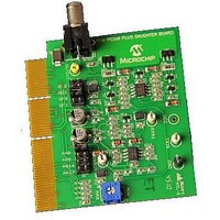
Consumer-band BPSK 7.2kbps PLM PICtail Plus Daughter Board Other
Manufacturer
Microchip Technology
Series
PICtail™ Plusr
Specifications of AC164142
Kit Application Type
Communication
Silicon Family Name
DsPIC
Kit Contents
2x Power-Line Soft-Modem PICtail Plus Daughter Boards, 2x High Voltage Adapter Cables, Info Sheet
Features
Operates On 5V And 9V
Rohs Compliant
Yes
Processor To Be Evaluated
dsPIC33F
Processor Series
dsPIC33F
Operating Supply Voltage
5 V, 9 V
Featured Product
AC164142 PICtail⢠Plus Daughter Board
Main Purpose
Interface, Power Line Transceiver
Embedded
No
Utilized Ic / Part
-
Primary Attributes
AC Power Line Transceiver, BPSK 7.2 Kbps
Secondary Attributes
Requires Explorer 16 Boards
Lead Free Status / Rohs Status
Lead free / RoHS Compliant
Available stocks
Company
Part Number
Manufacturer
Quantity
Price
Company:

Part Number:
AC164142
Manufacturer:
MICROCHIP
Quantity:
12 000
Part Number:
AC164142
Manufacturer:
BOARD
Quantity:
20 000


Consumer-band BPSK 7.2 kbps PLM PICtail™ Plus Daughter Board User’s Guide
DS70656A-page 26
Each frame (of 128 byte length) is composed of 16 bytes of preamble, 110 bytes of data
and 2 bytes of CRC. The demonstration application has two LCD views, which can be
toggled using switch S3 on the Explorer 16 Development Board:
• Frame statistics
• Application configuration (carrier frequency, modulation and baud rate)
3.2.2
This demonstration implements a network protocol with framing, CRC and a network
stack framework. The demonstration consists of a base station and a number of nodes.
Each node measures its potentiometer state (R6 on the Explorer 16 Development
Board) and sends the result to the station. The station displays the received values on
the LCD screen.
1. Program one Explorer 16 Development Board with the Station software.
2. Program one or more Explorer 16 Development boards with the Node software
3. Connect all boards to the power line and they will automatically start to
4. Turn the potentiometer, R6, on a node board. Observe how the value is updated
5. Use the S3 button to change the LCD screen contents. The LCD can display the
Debug information is sent via the serial port. The output can be observed by connecting
a serial port emulator (such as HyperTerminal) to the RS-232 port of the Explorer 16
Development Board. The UART configuration for this demonstration is:
• 115200 bps
• 8-N-1
• No flow control
3.2.3
This demonstration implements a raw data pipe for UART-to-UART connection over the
power line.
1. Connect a sender application (a PC or an embedded device) to the RS-232 port
2. The sender application may start transmitting data.
Data is immediately transferred over the power line and received by the receiver.
Sender and receiver may change roles at runtime. One-to-many configurations are
also valid.
The link is designed to appear raw and unframed to both RS-232 devices. Internally,
however, simple framing is used. Its purpose is to ensure that the receiver maintains
byte synchronization. Without framing it would not be practically feasible to guarantee
that the receiver and transmitter are byte-aligned. A frame consists of 10 preamble
characters (PRE = 0xA5), one Start-of-Frame character (SOF = 0x1B), a length byte,
up to 64 payload bytes, and a 16-bit ITUT CRC checksum. In total there is a 14 byte
overhead for each frame.
(each node must have a unique MAC address and must know the station MAC
address).
communicate.
on the node and station LCD screens.
current potentiometer state and packet statistics (frames transmitted, frames
received and errors).
of an Explorer 16 Development Board and a receiver application to the RS-232
port of the other Explorer 16 Development Board.
Sensor Monitoring Demonstration
Pipe Demonstration
© 2011 Microchip Technology Inc.
Related parts for AC164142
Image
Part Number
Description
Manufacturer
Datasheet
Request
R

Part Number:
Description:
Manufacturer:
Microchip Technology Inc.
Datasheet:
Part Number:
Description:
Manufacturer:
Microchip Technology Inc.
Datasheet:
Part Number:
Description:
Manufacturer:
Microchip Technology Inc.
Datasheet:
Part Number:
Description:
Manufacturer:
Microchip Technology Inc.
Datasheet:
Part Number:
Description:
Manufacturer:
Microchip Technology Inc.
Datasheet:
Part Number:
Description:
Manufacturer:
Microchip Technology Inc.
Datasheet:
Part Number:
Description:
Manufacturer:
Microchip Technology Inc.
Datasheet:
Part Number:
Description:
Manufacturer:
Microchip Technology Inc.
Datasheet: