AC164142 Microchip Technology, AC164142 Datasheet - Page 35
AC164142
Manufacturer Part Number
AC164142
Description
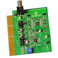
Consumer-band BPSK 7.2kbps PLM PICtail Plus Daughter Board Other
Manufacturer
Microchip Technology
Series
PICtail™ Plusr
Specifications of AC164142
Kit Application Type
Communication
Silicon Family Name
DsPIC
Kit Contents
2x Power-Line Soft-Modem PICtail Plus Daughter Boards, 2x High Voltage Adapter Cables, Info Sheet
Features
Operates On 5V And 9V
Rohs Compliant
Yes
Processor To Be Evaluated
dsPIC33F
Processor Series
dsPIC33F
Operating Supply Voltage
5 V, 9 V
Featured Product
AC164142 PICtail⢠Plus Daughter Board
Main Purpose
Interface, Power Line Transceiver
Embedded
No
Utilized Ic / Part
-
Primary Attributes
AC Power Line Transceiver, BPSK 7.2 Kbps
Secondary Attributes
Requires Explorer 16 Boards
Lead Free Status / Rohs Status
Lead free / RoHS Compliant
Available stocks
Company
Part Number
Manufacturer
Quantity
Price
Company:

Part Number:
AC164142
Manufacturer:
MICROCHIP
Quantity:
12 000
Part Number:
AC164142
Manufacturer:
BOARD
Quantity:
20 000


C.1
© 2011 Microchip Technology Inc.
FREQUENTLY ASKED QUESTIONS
Appendix C discusses common operational issues and methods to resolve them.
C.1.1
Possible reasons for the daughter boards to lose the communication link are:
C.1.1.1
Connecting daughter boards to power outlets on different phases may result in partial
or total loss of the communication link. If you observe that the daughter boards are not
able to communicate, try relocating the daughter boards to other power outlets or use
a signal coupler device to couple the communication signals across the phases, as
described in
C.1.1.2
Some of the configuration settings are hardware dependent and these settings should
match the hardware being used. Following configuration settings are hardware
dependent:
• Hi-Z signal polarity (PLM_OE, default: PLM_OE_ACTIVE_LOW_HIZ)
• Hi-Z signal pin (PLM_OE_LAT, default: LATF, #0)
• ADC input channel (PLM_ADC_CHNL, default: 8)
• Carrier frequency (PLM_FC, default: 129600)
C.1.1.3
The potentiometer (P1) is used to adjust the average output amplitude transmitted from
the daughter board. If the potentiometer is set too low the transmitted signal power may
not to be reliably detected by the other daughter board. It is preferable to set the
potentiometer value close to the "MAX" position (turn counter clockwise).
C.1.1.4
Daughter boards will not be able to communicate if they are programmed with
dissimilar settings for certain configuration options like carrier frequency, Forward Error
Correction (FEC), framing and baud rate.
C.1.1.5
Ensure that the jumpers at CS (JP2) and RX (JP3) are in place (default: JP2 - RF0, JP3
- AN8). Improper jumper settings can disable the transmitter or receiver sections of the
daughter board.
Appendix C. Troubleshooting Guide
The daughter boards are not able to communicate on the power
line. What can I do to fix the problem?
DAUGHTER BOARDS CONNECTED ON TWO DIFFERENT POWER
SUPPLY PHASES
SOFTWARE CONFIGURATION NOT COMPATIBLE WITH HARDWARE
DESIGN
POTENTIOMETER (P1) SET AT A LOW VALUE
DISSIMILAR CONFIGURATION SETTINGS
IMPROPER JUMPER CONFIGURATION
1.2 “Board
CONSUMER-BAND BPSK 7.2 kbps
PLM PICtail™ PLUS DAUGHTER
Setup”.
BOARD USER’S GUIDE
DS70656A-page 35
Related parts for AC164142
Image
Part Number
Description
Manufacturer
Datasheet
Request
R

Part Number:
Description:
Manufacturer:
Microchip Technology Inc.
Datasheet:
Part Number:
Description:
Manufacturer:
Microchip Technology Inc.
Datasheet:
Part Number:
Description:
Manufacturer:
Microchip Technology Inc.
Datasheet:
Part Number:
Description:
Manufacturer:
Microchip Technology Inc.
Datasheet:
Part Number:
Description:
Manufacturer:
Microchip Technology Inc.
Datasheet:
Part Number:
Description:
Manufacturer:
Microchip Technology Inc.
Datasheet:
Part Number:
Description:
Manufacturer:
Microchip Technology Inc.
Datasheet:
Part Number:
Description:
Manufacturer:
Microchip Technology Inc.
Datasheet: