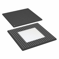
ADSP-21369KBPZ-3A Analog Devices Inc, ADSP-21369KBPZ-3A Datasheet - Page 40

ADSP-21369KBPZ-3A
Manufacturer Part Number
ADSP-21369KBPZ-3A
Description
IC,DSP,32-BIT,CMOS,BGA,256PIN,PLASTIC
Manufacturer
Analog Devices Inc
Series
SHARC®r
Type
Floating Pointr
Datasheet
1.ADSP-21369KBPZ-2A.pdf
(60 pages)
Specifications of ADSP-21369KBPZ-3A
Interface
DAI, DPI
Clock Rate
400MHz
Non-volatile Memory
ROM (768 kB)
On-chip Ram
256kB
Voltage - I/o
3.30V
Voltage - Core
1.20V
Operating Temperature
0°C ~ 70°C
Mounting Type
Surface Mount
Package / Case
256-BGA Exposed Pad, 256-eBGA, 256-HBGA
Lead Free Status / RoHS Status
Lead free / RoHS Compliant
For Use With
ADZS-21369-EZLITE - KIT EVAL EZ LITE ADDS-21369
Lead Free Status / RoHS Status
Lead free / RoHS Compliant
Available stocks
Company
Part Number
Manufacturer
Quantity
Price
Company:
Part Number:
ADSP-21369KBPZ-3A
Manufacturer:
TOREX
Quantity:
6 700
Company:
Part Number:
ADSP-21369KBPZ-3A
Manufacturer:
Analog Devices Inc
Quantity:
10 000
Part Number:
ADSP-21369KBPZ-3A
Manufacturer:
ADI/亚德诺
Quantity:
20 000
ADSP-21367/ADSP-21368/ADSP-21369
Pulse-Width Modulation Generators
Table 34. PWM Timing
Sample Rate Converter—Serial Input Port
The SRC input signals SCLK, frame sync (FS), and SDATA are
routed from the DAI_P20–1 pins using the SRU. Therefore, the
timing specifications provided in
DAI_P20–1 pins.
Table 35. SRC, Serial Input Port
1
Parameter
Switching Characteristics
t
t
Parameter
Timing Requirements
t
t
t
t
t
t
DATA, SCLK, FS can come from any of the DAI pins. SCLK and FS can also come via PCG or SPORTs. PCG’s input can be either CLKIN or any of the DAI pins.
PWMW
PWMP
SRCSFS
SRCHFS
SRCSD
SRCHD
SRCCLKW
SRCCLK
1
1
1
1
OUTPUTS
PWM
FS Setup Before SCLK Rising Edge
FS Hold After SCLK Rising Edge
SDATA Setup Before SCLK Rising Edge
SDATA Hold After SCLK Rising Edge
Clock Width
Clock Period
PWM Output Pulse Width
PWM Output Period
DAI_P20–1
DAI_P20–1
DAI_P20–1
(SDATA)
(SCLK)
(FS)
Table 35
are valid at the
t
Figure 28. SRC Serial Input Port Timing
PWMW
Rev. E | Page 40 of 60 | July 2009
t
Figure 27. PWM Timing
SRCCLKW
t
SRCSD
t
SRCSFS
SAMPLE EDGE
t
PWMP
Min
t
2 × t
PCLK
– 2
PCLK
– 1.5
t
t
SRCHFS
SRCHD
t
SRCCLK
Min
4
5.5
4
5.5
(t
t
PCLK
PCLK
× 4
× 4) ÷ 2 – 1
Max
(2
(2
16
16
– 2) × t
– 1) × t
Max
PCLK
PCLK
– 2
– 1.5
Unit
ns
ns
Unit
ns
ns
ns
ns
ns
ns


