SP7600EB Exar Corporation, SP7600EB Datasheet - Page 10
SP7600EB
Manufacturer Part Number
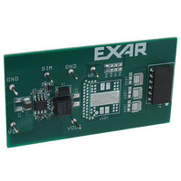
SP7600EB
Description
EVAL BOARD FOR SP7600
Manufacturer
Exar Corporation
Specifications of SP7600EB
Current - Output / Channel
2A
Outputs And Type
1, Non-Isolated
Features
PWM Brightness control
Voltage - Input
4.5 ~ 29 V
Utilized Ic / Part
SP7600
Maximum Operating Temperature
+ 85 C
Minimum Operating Temperature
- 40 C
Product
Display Modules
Core Chip
SP7600
No. Of Outputs
1
Output Current
2A
Output Voltage
200mV
Dimming Control Type
PWM
Development Tool Type
Hardware - Eval/Demo Board
Mcu Supported Families
SP7600
Lead Free Status / RoHS Status
Contains lead / RoHS non-compliant
Voltage - Output
-
Lead Free Status / Rohs Status
Lead free / RoHS Compliant
Other names
1016-1233


a string of series connected LEDs Vo equals
total Vf)
ΔI
30% of Io)
Inductor Isat and Irms must allow sufficient
safeguard over output current Io. As a rule of
thumb these parameters should be 50%
higher than Io. Where high efficiency is
required a low DCR inductor should be used.
I
Select the input capacitor for capacitanceand
ripple current rating. Use the capacitances
listed in the table 1 as a starting point and if
needed increase Cin.
Calculate the ripple current requirement from:
Where
Ceramic capacitors are recommended for input
filtering due to their low Equivalent Series
© 2009 Exar Corporation
NPUT CAPACITOR SELECTION
L
is inductor current ripple (nominally set to
0.71 to 1.2
D =
Equ.4:
I
<0.7
>1.2
O
(A)
Vin
Vo
Table 1: Cin Selection
Irip
=
Io
×
D
×
Cin (µF)
1 ( D
2 x 4.7
−
2.2
4.7
)
2
2
A
A
2
2
9
9
V
V
10/13
N
N
o
o
n
n
Resistance
inductance (ESL) and small form factor.
S
Select the Schottky D1 for Voltage rating VR
and current rating If. Recommended schottky
diode
applications is 30V and 40V respectively.
Current rating can be calculated from:
Note that in applications where duty cycle is
low,
percentage of converter losses. In order to
improve the efficiency in these applications
choose a Schottky that meets the calculated
current rating and has a lower Vf.
F
R2 is part of SP7600 loop compensation
network. Use a 30k R2 for Vin of 20V and
larger. Use R2 of 60K for Vin less than 20V.
C
This is the decoupling capacitor for the power
supply for the internal driver. Use a 0.1uF and
place as closely to VDR and SVIN pins as
possible.
-
-
S
S
EEDBACK RESISTOR
CHOTTKY RECTIFIER SELECTION
APACITOR
y
y
n
n
c
c
Schottky
.
.
voltage
B
B
Equ.5 :
u
u
C5
c
c
k
k
(ESR),
H
H
rating
losses
i
i
If
g
g
h
h
≥ 1
RFB
P
P
o
o
for
Equivalent
comprise
−
w
w
Vin
Vo
e
e
r
r
12V
×
L
L
Io
E
E
S
S
D
D
P
and
P
a
Rev. 2.0.0
D
D
7
7
r
r
Series
6
6
larger
i
i
v
v
0
0
24V
e
e
0
0
r
r
Related parts for SP7600EB
Image
Part Number
Description
Manufacturer
Datasheet
Request
R

Part Number:
Description:
2amp, 29v Buck Converter For Led Driver Applications
Manufacturer:
Exar Corporation
Datasheet:
Part Number:
Description:
BiCMOS Fixed, Quad, Voltage Output, Single or Dual Supply 8-Bit Digital-to-Analog Converter
Manufacturer:
Exar Corporation
Datasheet:
Part Number:
Description:
Manufacturer:
Exar Corporation
Datasheet:
Part Number:
Description:
Voltage-Controlled Oscillator
Manufacturer:
Exar Corporation
Datasheet:
Part Number:
Description:
INTEGRATED LINE TRANSMITTER
Manufacturer:
Exar Corporation
Datasheet:
Part Number:
Description:
Monolithic Function Generator
Manufacturer:
Exar Corporation
Datasheet:
Part Number:
Description:
CMOS Microprocessor Compatible Double-Buffered 12-Bit Digital-to-Analog Converter
Manufacturer:
Exar Corporation
Datasheet:
Part Number:
Description:
CMOS 6 BIT HIGH SPEED ANALOG TO DIGITAL CONVERTER
Manufacturer:
Exar Corporation
Datasheet:
Part Number:
Description:
Manufacturer:
Exar Corporation
Datasheet:
Part Number:
Description:
Manufacturer:
Exar Corporation
Datasheet:
Part Number:
Description:
8-Channel, Voltage Output 10 MHz Input Bandwidth 8-Bit Multiplying DACs with Serial Digital Data Por
Manufacturer:
Exar Corporation
Datasheet:
Part Number:
Description:
15 V CMOS Multiplying10-Bit Digital-to-Analog Converter
Manufacturer:
Exar Corporation
Datasheet:
Part Number:
Description:
Monolithic Function Generator
Manufacturer:
Exar Corporation
Datasheet: