ADNB-6002-EV Avago Technologies US Inc., ADNB-6002-EV Datasheet - Page 36
ADNB-6002-EV
Manufacturer Part Number
ADNB-6002-EV
Description
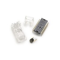
OPT SENS BUNDLE W/A-6000 TL CLIP
Manufacturer
Avago Technologies US Inc.
Specifications of ADNB-6002-EV
Description/function
Laser Mouse Bundle
Interface Type
SPI
Product
Display Modules
Touch Panel
No Touch Panel
For Use With/related Products
ADNS-6000
Lead Free Status / RoHS Status
Lead free / RoHS Compliant
Lead Free Status / RoHS Status
Lead free / RoHS Compliant, Lead free / RoHS Compliant


Frame_Period_Max_Bound_Lower
Access: Read/Write
Frame_Period_Max_Bound_Upper
Access: Read/Write
Data Type: 16-bit unsigned integer.
USAGE: This value sets the maximum frame period (the MINIMUM frame rate) which may be selected by the automatic
frame rate control, or sets the actual frame period when operating in manual mode. Units are clock cycles. The formula
is
Frame Rate = Clock Frequency / Register value
To read from the registers, read Upper first followed by Lower. To write to the registers, write Lower first, followed by
Upper. To set the frame rate manually, disable automatic frame rate mode via the Extended_Config register and write
the desired count value to these registers.
Writing to the Frame_Period_Max_Bound_Upper and Lower registers also activates any new values in the following
registers:
• Frame_Period_Max_Bound_Upper and Lower
• Frame_Period_Min_Bound_Upper and Lower
• Shutter_Max_Bound_Upper and Lower
Any data written to these registers will be saved but will not take effect until the write to the Frame_Period_Max_
Bound_Upper and Lower is complete. After writing to this register, two complete frame times are required to
implement the new settings. Writing to any of the above registers before the implementation is complete may put
the chip into an undefined state requiring a reset. The “Busy” bit in the Extended_Config register may be used in lieu
of a timer to determine when it is safe to write. See the Extended_Config register for more details.
The following table lists some Frame_Period values for popular frame rates (clock rate = 24MHz). In addition, the three
bound registers must also follow this rule when set to non-default values:
Frame_Period_Max_Bound ≥ Frame_Period_Min_Bound + Shutter_Max_Bound.
36
Field
Bit
Field
Bit
FBM
7
FBM
15
7
7
FBM
6
FBM
14
6
6
FBM
Address: 0x19
Default Value: 0x90
Address: 0x1A
Default Value: 0x65
5
FBM
13
5
5
FBM
FBM
4
13
4
4
FBM
FBM
3
11
3
3
FBM
FBM
2
2
10
2
FBM
FBM
1
1
9
1
FBM
FBM
0
0
8
0
Related parts for ADNB-6002-EV
Image
Part Number
Description
Manufacturer
Datasheet
Request
R

Part Number:
Description:
OPTICAL MOUSE EVALUATION KIT
Manufacturer:
Avago Technologies US Inc.
Datasheet:

Part Number:
Description:
Display Modules & Development Tools Bundle w/Trim Lens
Manufacturer:
Avago Technologies US Inc.

Part Number:
Description:
Display Modules & Development Tools Bundle w/Trim Lens
Manufacturer:
Avago Technologies US Inc.

Part Number:
Description:
Display Modules & Development Tools Mouse sensor
Manufacturer:
Avago Technologies US Inc.
Part Number:
Description:
Display Modules & Development Tools Mouse sensor
Manufacturer:
Avago Technologies US Inc.

Part Number:
Description:
Display Modules & Development Tools Bundle w/Trim Lens
Manufacturer:
Avago Technologies US Inc.

Part Number:
Description:
Display Modules & Development Tools Sensor+Round Lens
Manufacturer:
Avago Technologies US Inc.
Part Number:
Description:
Display Modules & Development Tools Mouse sensor
Manufacturer:
Avago Technologies US Inc.

Part Number:
Description:
Display Modules & Development Tools Mouse sensor
Manufacturer:
Avago Technologies US Inc.

Part Number:
Description:
Display Modules & Development Tools Bundle w/Trim Lens
Manufacturer:
Avago Technologies US Inc.

Part Number:
Description:
OPTOCOUPLER GATE DRV 2A 16-SOIC
Manufacturer:
Avago Technologies US Inc.
Datasheet:
Part Number:
Description:
OPTOCOUPLER 2CH 2.5A 16-SOIC
Manufacturer:
Avago Technologies US Inc.
Datasheet:

Part Number:
Description:
OPTOCOUPLER GATE DRV 0.4A 16SOIC
Manufacturer:
Avago Technologies US Inc.
Datasheet:

Part Number:
Description:
OPTOCOUPLER 2.0A 250KHZ 8-DIP
Manufacturer:
Avago Technologies US Inc.
Datasheet:

Part Number:
Description:
OPTOCOUPLER 2.0A 250KHZ GW 8-SMD
Manufacturer:
Avago Technologies US Inc.
Datasheet: