ADNB-6002-EV Avago Technologies US Inc., ADNB-6002-EV Datasheet - Page 7
ADNB-6002-EV
Manufacturer Part Number
ADNB-6002-EV
Description
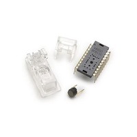
OPT SENS BUNDLE W/A-6000 TL CLIP
Manufacturer
Avago Technologies US Inc.
Specifications of ADNB-6002-EV
Description/function
Laser Mouse Bundle
Interface Type
SPI
Product
Display Modules
Touch Panel
No Touch Panel
For Use With/related Products
ADNS-6000
Lead Free Status / RoHS Status
Lead free / RoHS Compliant
Lead Free Status / RoHS Status
Lead free / RoHS Compliant, Lead free / RoHS Compliant


Laser Output Power
LASER Output Power
The laser beam output power as measured at the navi-
gation surface plane is specified below. The following
conditions apply:
1. The system is adjusted according to the above proce-
2. The system is operated within the recommended operat-
3. The VDD3 value is no greater than 50mV above its value
4. No allowance for optical power meter accuracy is as-
Disabling the LASER
LASER_NEN is connected to the base of a PNP transistor
which when ON connects V
operation, LASER_NEN is low. In the case of a fault
condition (ground at XY_LASER or RBIN), LASER_NEN
goes high to turn the transistor off and disconnect V
from the LASER.
Microcontroller
Figure 6. Single Fault Detection and Eye-safety Feature Block Diagram
7
Parameter
Laser output power
dure.
ing temperature range.
at the time of adjustment.
sumed.
RESET
NPD
DD3
Symbol
LOP
voltage sense
fault control
current set
to the LASER. In normal
ADNS-6000
block
DRIVER
LASER
RBIN
Minimum
DD3
Maximum
716
Single Fault Detection
ADNS-6000 is able to detect a short circuit, or fault,
condition at the RBIN and XY_LASER pins, which could
lead to excessive laser power output. A low resistance
path to ground on either of these pins will trigger the
fault detection circuit, which will turn off the laser drive
current source and set the LASER_NEN output high. When
used in combination with external components as shown
in the block diagram below, the system will prevent
excess laser power for a single short to ground at RBIN or
XY_LASER by shutting off the laser. Refer to the PC board
layout notes for recommendations to reduce the chance
of high resistance paths to ground existing due to PC
board contamination.
In addition to the continuous fault detection described
above, an additional test is executed automatically
whenever the LP_CFG0 register is written to. This test
will check for a short to ground on the XY_LASER pin, a
short to VDD3 on the XY_LASER pin, and will test the fault
detection circuit on the XY_LASER pin.
VDD3
GND
Units
uW
LASER_NEN
XY_LASER
Notes
Per conditions above
VDD3
LASER
Related parts for ADNB-6002-EV
Image
Part Number
Description
Manufacturer
Datasheet
Request
R

Part Number:
Description:
OPTICAL MOUSE EVALUATION KIT
Manufacturer:
Avago Technologies US Inc.
Datasheet:

Part Number:
Description:
Display Modules & Development Tools Bundle w/Trim Lens
Manufacturer:
Avago Technologies US Inc.

Part Number:
Description:
Display Modules & Development Tools Bundle w/Trim Lens
Manufacturer:
Avago Technologies US Inc.

Part Number:
Description:
Display Modules & Development Tools Mouse sensor
Manufacturer:
Avago Technologies US Inc.
Part Number:
Description:
Display Modules & Development Tools Mouse sensor
Manufacturer:
Avago Technologies US Inc.

Part Number:
Description:
Display Modules & Development Tools Bundle w/Trim Lens
Manufacturer:
Avago Technologies US Inc.

Part Number:
Description:
Display Modules & Development Tools Sensor+Round Lens
Manufacturer:
Avago Technologies US Inc.
Part Number:
Description:
Display Modules & Development Tools Mouse sensor
Manufacturer:
Avago Technologies US Inc.

Part Number:
Description:
Display Modules & Development Tools Mouse sensor
Manufacturer:
Avago Technologies US Inc.

Part Number:
Description:
Display Modules & Development Tools Bundle w/Trim Lens
Manufacturer:
Avago Technologies US Inc.

Part Number:
Description:
OPTOCOUPLER GATE DRV 2A 16-SOIC
Manufacturer:
Avago Technologies US Inc.
Datasheet:
Part Number:
Description:
OPTOCOUPLER 2CH 2.5A 16-SOIC
Manufacturer:
Avago Technologies US Inc.
Datasheet:

Part Number:
Description:
OPTOCOUPLER GATE DRV 0.4A 16SOIC
Manufacturer:
Avago Technologies US Inc.
Datasheet:

Part Number:
Description:
OPTOCOUPLER 2.0A 250KHZ 8-DIP
Manufacturer:
Avago Technologies US Inc.
Datasheet:

Part Number:
Description:
OPTOCOUPLER 2.0A 250KHZ GW 8-SMD
Manufacturer:
Avago Technologies US Inc.
Datasheet: