8808A/SU 120V Fluke Electronics, 8808A/SU 120V Datasheet - Page 50
8808A/SU 120V
Manufacturer Part Number
8808A/SU 120V
Description
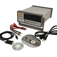
USB CABLE KIT SW DMM 5.5 RES
Manufacturer
Fluke Electronics
Type
Digital (DMM)r
Datasheet
1.8808A_120V.pdf
(100 pages)
Specifications of 8808A/SU 120V
Includes
Test Leads
Style
Bench
Display Digits
5.5
Display Type
VFD, Dual
Display Count
200000
Function
Voltage, Current, Resistance, Frequency
Functions, Extra
Continuity, dB, Diode Test
Features
Hold, Min/Max, RS-232 Port
Ranging
Auto/Manual
Response
True RMS
Lead Free Status / RoHS Status
Not applicable / RoHS non-compliant
Other names
614-1069


8808A
Users Manual
3-16
Making a Triggered Measurement
Setting the Trigger Mode
Connecting to an External Trigger
The Meter features a trigger function that allows you to select a measurement trigger
source. When the trigger mode is set to 3 or 5, the delay between receiving the trigger
and the start of a measurement is 400 ms. Refer to Chapter 1 for trigger delay response
specifications. Upon completion of each measurement, a “measurement-complete” signal
(low-true pulse) is sent to the external trigger terminal on the rear panel. See the
“Electrical Specifications” section in Chapter 1 for information on this signal.
The following sections discuss triggering the Meter automatically using its internal
trigger, or externally using the trigger key on the front panel and the trigger terminal on
the rear panel.
There are five possible sources for triggering a measurement:
To select a trigger source:
The Meter provides two external trigger connection methods for different operation
modes. Table 3-4 shows the layout of the TRIG/IO_RS232 connector.
1. Press Q then J.
2. Press U or V to choose the trigger mode.
3. Press R and hold for 2 seconds to save the selected mode.
Mode 1 is automatic. Measurements are triggered internally and are continuous
and occur as fast as the configuration will allow.
Mode 2 is triggered without delay using J.
Mode 3 is triggered with delay using J.
Mode 4 is triggered without delay by an external signal.
Mode 5 is triggered with delay by an external signal.
Figure 3-11. Diode Test
2W/4W
1000V
mA
750V
LO
HI
200 mA
MAX
MAX
V
INPUT
1000 V
600 V
500 V pk
10 A
MAX
1V
CAT I
CAT II
SENSE
4 W
300V
10A
LO
HI
eue16.eps