8808A/SU 120V Fluke Electronics, 8808A/SU 120V Datasheet - Page 94
8808A/SU 120V
Manufacturer Part Number
8808A/SU 120V
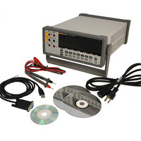
Description
USB CABLE KIT SW DMM 5.5 RES
Manufacturer
Fluke Electronics
Type
Digital (DMM)r
Datasheet
1.8808A_120V.pdf
(100 pages)
Specifications of 8808A/SU 120V
Includes
Test Leads
Style
Bench
Display Digits
5.5
Display Type
VFD, Dual
Display Count
200000
Function
Voltage, Current, Resistance, Frequency
Functions, Extra
Continuity, dB, Diode Test
Features
Hold, Min/Max, RS-232 Port
Ranging
Auto/Manual
Response
True RMS
Lead Free Status / RoHS Status
Not applicable / RoHS non-compliant
Other names
614-1069


A-4
8808A
Users Manual
REL
HOLD
Primary
Display
The lead from the internal measuring circuitry of the meter to the LO terminal (on the
front panel) is the same for both voltage and current measurements. The resistance of this
lead is approximately .003 ohm. If current is being measured, therefore, a voltage drop
will occur in the resistance that is common to both circuits. This internal resistance, when
added to the external resistance of the lead from the COM input terminal will affect the
accuracy of the voltage reading. For instance, if the external lead resistance is .007 ohm,
the "total" common resistance is .010 ohm. If there is 1 A of current, the voltage reading
would be affected by
Depending on the circumstances, this may be significant.
If you want to measure dc voltage on an input signal in the primary display and dc
current in the secondary display, proceed as follows:
1. Turn the Meter on
2. Press D to select the dc voltage function for the primary display.
3. Press Q then E to select the dc current function for the secondary display.
4. Connect the leads to the test circuit as shown in Figure A-2 and read the
(1 A x.01ohm ) = .01 V or 10 m V.
measurements on the display. Although current will be displayed as negative, it is in
fact positive when interpreted according to current flow convention.
Figure A-2. DC Voltage and DC Current Measurement on Input Signal
Resistance
Actual Value
Secondary
Display
Table A-2. Sample Dual Display Applications (cont.)
Select and sort resistors. (See also "Using the Compare Function"
in Chapter 3.)
Show actual measurement while holding a previous, stable
measurement on the primary display
2W/4W
1000V
mA
750V
LO
HI
200 mA
MAX
MAX
V
INPUT
1000 V
600 V
500 V pk
10 A
MAX
1V
CAT I
CAT II
SENSE
4 W
300V
LO
10A
HI
Applications
8808A
5-1/2 DIGIT MULTIMETER
eue27.eps