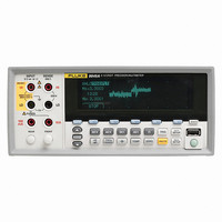
8846A/SU 120V Fluke Electronics, 8846A/SU 120V Datasheet - Page 86

8846A/SU 120V
Manufacturer Part Number
8846A/SU 120V
Description
PREC MLTMTR 6.5DIGI USB W/SFTWRE
Manufacturer
Fluke Electronics
Type
Digital (DMM)r
Specifications of 8846A/SU 120V
Includes
Test Leads
Style
Bench
Display Digits
6.5
Display Type
VFD, Dual
Display Count
Varies
Function
Voltage, Current, Resistance, Capacitance, Temperature, Frequency
Functions, Extra
Continuity, dB, Diode Test
Features
Memory, RS-232, USB Port
Ranging
Manual
Response
Average
Lead Free Status / RoHS Status
Contains lead / RoHS compliant by exemption
Other names
2675344
614-1003
614-1003
8845A/8846A
Users Manual
4-18
Connecting an External Trigger
Monitoring the Measurement-Complete Signal
1. Press Lto display the measurement setup menu.
2. Press the TRIGGER soft key.
3. Press the soft key labeled #SAMPLES.
4. Use the soft keys to set the number of samples between 1 and 50,000.
5. Press ENTER.
The TRIG I/O jack on the Meter’s rear panel is used to connect to an external trigger
signal. The falling edge of a TTL signal will trigger the Meter to start taking
measurements, if the Meter is in external trigger mode.
Figure 4-9 indicates the purpose of the three pins in the TRIG I/O connector.
In addition to being a trigger input, the TRIG I/O jack on the Meter’s rear panel also
provides a signal indicating the completion of a measurement cycle. A falling edge of a
TTL signal indicates a measurement cycle is complete. See Figure 4-9 above to identify
which pins on the TRIG I/O connector are used to sense the measurement-complete
signal.
Select the digit in the value by pressing either <-- or -->.
With the digit selected, press the soft key labeled -- to decrement the digit or ++ to
increment the character.
Pin 1: Trigger In
Figure 4-9. TRIG I/O Pin-out Description
TRIG I/O
Pin 2: Signal Ground
Pin 3: Measure Complete Out
caw059.eps


