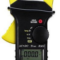
ACDC-620T Amprobe, ACDC-620T Datasheet - Page 55

ACDC-620T
Manufacturer Part Number
ACDC-620T
Description
DMM CLAMP-ON TRMS
Manufacturer
Amprobe
Type
Digital (DMM)r
Datasheet
1.ACDC-620T.pdf
(65 pages)
Specifications of ACDC-620T
Includes
Battery, Case, Test Leads
Style
Clamp
Display Digits
4
Display Type
LCD, Bar Graph
Display Count
4000
Function
Voltage, Current, Resistance, Capacitance, Temperature
Functions, Extra
Continuity, Diode Test
Features
Auto Off, Hold, Min/Max/Ave, Sleep
Ranging
Auto/Manual
Response
True RMS
Frequency
45 Hz to 65 Hz
Maximum Ac Current
1 KA
True Rms
Yes
Voltage
400 V/100 V
Lead Free Status / RoHS Status
Contains lead / RoHS compliant by exemption
Other names
2730822
c
WAVEFORMCOMPARISON
Ta b l e3. Illustrates the relationship between AC and DC components for common
waveforms, and compares readings for TRUE RMS meters and average-responding
meters. For example, consider the first waveform, a 1414V (zero-to-peak) sine wave.
Both this Clamp-on meter and RMS-calibrated average-responding meters display
the correct RMS reading of100.0V (the DC component equals 0). However, consider
the 200V (peak-to-peak) square wave, both types of meter correctly measure the DC
component (oV). The clamp meter correctly measures the AC component (100.0V).
The average-responding meter measures 111.1V, which amounts to an 11% error.
The conversion factors in Table 3 show the differences between average sensing
instruments and true RMS instrument measurements.
54


