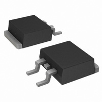
MBRB3030CTLG ON Semiconductor, MBRB3030CTLG Datasheet - Page 4

MBRB3030CTLG
Manufacturer Part Number
MBRB3030CTLG
Description
DIODE SCHOTTKY 30V 15A D2PAK
Manufacturer
ON Semiconductor
Series
SWITCHMODE™r
Datasheet
1.MBRB3030CTLG.pdf
(8 pages)
Specifications of MBRB3030CTLG
Voltage - Forward (vf) (max) @ If
440mV @ 15A
Current - Reverse Leakage @ Vr
2mA @ 30V
Current - Average Rectified (io) (per Diode)
15A
Voltage - Dc Reverse (vr) (max)
30V
Diode Type
Schottky
Speed
Fast Recovery =< 500ns, > 200mA (Io)
Diode Configuration
1 Pair Common Cathode
Mounting Type
Surface Mount
Package / Case
D²Pak, TO-263 (2 leads + tab)
Lead Free Status / RoHS Status
Lead free / RoHS Compliant
Reverse Recovery Time (trr)
-
Available stocks
Company
Part Number
Manufacturer
Quantity
Price
Company:
Part Number:
MBRB3030CTLG
Manufacturer:
ON
Quantity:
12 500
Part Number:
MBRB3030CTLG
Manufacturer:
ON/安森美
Quantity:
20 000
Modeling Reverse Energy Characteristics
of Power Rectifiers
Prepared by: David Shumate & Larry Walker
ON Semiconductor Products Sector
applications where the reverse energy requirements often
vary dramatically based on the operating conditions of the
application circuit. A characterization method was devised
using the Unclamped Inductive Surge (UIS) test technique.
By testing at only a few different operating conditions
(i.e. different inductor sizes) a safe operating range can be
established for a device. A relationship between peak
avalanche current and inductor discharge time was
established. Using this relationship and circuit parameters,
the part applicability can be determined. This technique
offers a power supply designer the total operating conditions
for a device as opposed to the present single−data−point
approach.
switching circuitry, large voltage spikes due to parasitic
inductance can propagate throughout the circuit, resulting in
catastrophic device failures. Concurrent with this, in an
effort to provide low−loss power rectifiers, i.e., devices with
lower forward voltage drops, Schottky technology is being
Power semiconductor rectifiers are used in a variety of
In today’s modern power supplies, converters and other
INTRODUCTION
+
V
−
ABSTRACT
FREE−WHEELING
DIODE
DRAIN VOLTAGE
HIGH SPEED SWITCH
Figure 10. Simplified UIS Test Circuit
CHARGE INDUCTOR
http://onsemi.com
MBRB3030CTL
4
DUT
applied to devices used in this switching power circuitry.
This technology lends itself to lower reverse breakdown
voltages. This combination of high voltage spikes and low
reverse breakdown voltage devices can lead to reverse
energy destruction of power rectifiers in their applications.
This phenomena, however, is not limited to just Schottky
technology.
semiconductor manufacturers attempt to characterize their
devices with respect to reverse energy robustness. The
typical reverse energy specification, if provided at all, is
usually given as energy−to−failure (mJ) with a particular
inductor specified for the UIS test circuit. Sometimes the
peak reverse test current is also specified. Practically all
reverse energy characterizations are performed using the
UIS test circuit shown in Figure 10. Typical UIS voltage and
current waveforms are shown in Figure 11.
characterization than the above mentioned one−point
approach, a more comprehensive method for characterizing
these devices was developed. A designer can use the given
information to determine the appropriateness and safe
operating area (SOA) of the selected device.
In order to meet the challenges of these situations, power
In order to provide the designer with a more extensive
GATE
VOLTAGE
DRAIN CURRENT
INDUCTOR
CHARGE
SWITCH


