A165E-M-03U Omron, A165E-M-03U Datasheet - Page 162
A165E-M-03U
Manufacturer Part Number
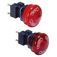
A165E-M-03U
Description
E-stop,non-lighted,40diameter
Manufacturer
Omron
Specifications of A165E-M-03U
Contact Configuration
3PST-NC
Switch Operation
Pushlock Turn Reset
Contact Voltage Ac Nom
250V
Contact Voltage Dc Nom
30V
Contact Current Max
5A
Actuator Style
Round
Control Type
Emergency Stop
Contact Form
3PST - NC
Contact Rating
10 mAmps
Illuminated
N
Lead Free Status / RoHS Status
Lead free / RoHS Compliant
Lead Free Status / RoHS Status
Lead free / RoHS Compliant


Mounting the Operation Unit on the
Panel
Insert the Operation Unit (Pushbutton, etc.) from the front surface of
the panel, insert the Lock Ring and the mounting nut from the termi-
nal side, then tighten the nut. Before tightening, check that the rubber
washer is present between the Pushbutton Unit and the panel.
When using a Legend Plate Frame, put one rubber washer each
between the Legend Plate Frame and the panel and between the
Operation Unit and the Legend Plate Frame. (One rubber washer will
be provided when one Legend Plate Frame is ordered.)
Align the Lock Ring with the groove in the casing, then insert the
Lock Ring so that its edge is located on the panel side.
Tighten the mounting nut at a torque of 0.98 to 1.96 N·m.
When using a Lock Ring, replace with the supplied Lock Ring, insert
the projecting part into the lock slot, and then tighten the mounting
nut.
When the panel cutout dimension is 25 dia., remove the supplied
rubber washer and mount the 25-dia. Ring as shown below. (Since
the A22Z-R25 is not attached to the main body, order separately.)
160
Hold here
Lock Ring
Panel
Mounting nut
Rubber washer
Panel
Lock Ring
22.3 dia.
22.3 dia.
22 dia.
25 dia.
25 dia.
Mounting nut
25-dia. Ring
Operation Unit
(A22Z-R25)
Pro-
jecting
part
Panel
Lock Ring
Mounting the Switch on the
Pushbutton Unit
Insert the Pushbutton Unit into the Switch Unit, aligning the arrow
mark inscribed on the Case with the lever on the Switch Blocks, then
move the lever in the direction indicated by the arrow in the following
figure.
Removing the Switch
Move the lever in the direction indicated by the arrow in the following
figure, then pull the Pushbutton Unit or the Switch Blocks.
Since the lever has a hole with an inside diameter of 6.5 mm, the
lever can be moved in the specified direction by inserting a screw-
driver into the hole and then moving the screwdriver.
Projection, Fall-guard
Grip and rotate the Color Cap with your fingers.
Mounting/Replacing the Color
Cap
Operation Unit
Arrow mark
Screwdriver
Lever
Related parts for A165E-M-03U
Image
Part Number
Description
Manufacturer
Datasheet
Request
R

Part Number:
Description:
SWITCH, EMERGENCY STOP, DPST-NC, 250VAC
Manufacturer:
Omron
Datasheet:

Part Number:
Description:
ESTOP OPERATOR
Manufacturer:
Omron
Datasheet:
Part Number:
Description:
E-stop,non-lighted,1NC,40diamt
Manufacturer:
Omron
Datasheet:
Part Number:
Description:
ESTOP OPERATOR
Manufacturer:
Omron
Datasheet:
Part Number:
Description:
1 NC CONTACT
Manufacturer:
Omron
Datasheet:

Part Number:
Description:
2 NC CONTACTS
Manufacturer:
Omron
Datasheet:
Part Number:
Description:
2 NC CONTACTS
Manufacturer:
Omron
Datasheet:
Part Number:
Description:
ESTOP OPERATOR
Manufacturer:
Omron
Datasheet:
Part Number:
Description:
E-stop,lighted,1NC,40diameter
Manufacturer:
Omron
Datasheet:
Part Number:
Description:
E-stop,lighted,2NC,40diameter
Manufacturer:
Omron
Datasheet:

Part Number:
Description:
SWITCH PB SQUARE MOM SPDT GREEN
Manufacturer:
Omron
Datasheet:
Part Number:
Description:
SWITCH PB SQUARE MOM SPDT WHITE
Manufacturer:
Omron
Datasheet:
Part Number:
Description:
SWITCH PB SQUARE MOM SPDT YELLOW
Manufacturer:
Omron
Datasheet:
Part Number:
Description:
SWITCH PB RECTANG MOM SPDT BLUE
Manufacturer:
Omron
Datasheet:
Part Number:
Description:
SWITCH PB RECTANG MOM SPDT YEL
Manufacturer:
Omron
Datasheet: