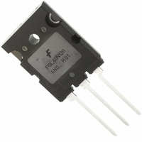
FGL40N120ANDTU Fairchild Semiconductor, FGL40N120ANDTU Datasheet - Page 6

FGL40N120ANDTU
Manufacturer Part Number
FGL40N120ANDTU
Description
IGBT NPT 1200V 64A TO264
Manufacturer
Fairchild Semiconductor
Datasheet
1.FGL40N120ANDTU.pdf
(9 pages)
Specifications of FGL40N120ANDTU
Igbt Type
NPT
Voltage - Collector Emitter Breakdown (max)
1200V
Vce(on) (max) @ Vge, Ic
3.2V @ 15V, 40A
Current - Collector (ic) (max)
64A
Power - Max
500W
Input Type
Standard
Mounting Type
Through Hole
Package / Case
TO-264
Configuration
Single
Collector- Emitter Voltage Vceo Max
1200 V
Maximum Gate Emitter Voltage
+/- 25 V
Maximum Operating Temperature
+ 150 C
Continuous Collector Current Ic Max
64 A
Minimum Operating Temperature
- 55 C
Mounting Style
Through Hole
Transistor Type
IGBT
Dc Collector Current
64A
Collector Emitter Voltage Vces
1.2kV
Power Dissipation Pd
500W
Collector Emitter Voltage V(br)ceo
1.2kV
Operating Temperature Range
-55°C To +150°C
Rohs Compliant
Yes
Lead Free Status / RoHS Status
Lead free / RoHS Compliant
Other names
FGL40N120ANDTU_NL
FGL40N120ANDTU_NL
FGL40N120ANDTU_NL
Available stocks
Company
Part Number
Manufacturer
Quantity
Price
Company:
Part Number:
FGL40N120ANDTU
Manufacturer:
FSC
Quantity:
4 500
Company:
Part Number:
FGL40N120ANDTU
Manufacturer:
FSC
Quantity:
1 875
Part Number:
FGL40N120ANDTU
Manufacturer:
FAIRCHILD/ن»™ç«¥
Quantity:
20 000
FGL40N120AND Rev. A2
Typical Performance Characteristics
Figure 13. Switching Loss vs. Collector Current
Figure 15. SOA Characteristics
Figure 17. Forward Characteristics
0.01
100
0.1
100
0.1
10
0.1
10
10
1
1
1
0.1
0
Common Emitter
V
T
T
Single Nonrepetitive
Pulse Tc = 25
Curves must be derated
linearly with increase
in temperature
Ic MAX (Continuous)
20
Ic MAX (Pulsed)
C
C
GE
= 25
= 125
=
T
±
J
15V, R
°
= 125
C
°
1
C
30
Collector - Emitter Voltage, V
1
o
G
C
o
C
= 5
Collector Current, I
Forward Voltage , V
Ω
40
2
T
J
= 25
10
DC Operation
50
3
o
C
60
C
F
[A]
4
100
[V]
T
T
1ms
CE
C
C
= 125
= 25
70
[V]
100
5
o
o
C
Eon
Eoff
µ
C
s
1000
80
50
µ
s
6
(Continued)
6
Figure 14. Gate Charge Characteristics
Figure 16. Turn-Off SOA
Figure 18. Reverse Recovery Current
100
16
14
12
10
10
10
8
6
4
2
0
1
8
6
4
2
0
0
1
0
Common Emitter
R
T
C
L
= 15
= 25
10
Ω
°
C
50
Collector-Emitter Voltage, V
di/dt = 200A/
20
10
Forward Current , I
Gate Charge, Q
Safe Operating Area
V
GE
100
= 15V, T
30
µ
s
di/dt = 100A/
Vcc = 200V
C
40
= 125
150
100
g
[nC]
F
o
[A]
C
50
CE
400V
µ
s
[V]
200
600V
60
www.fairchildsemi.com
1000
250
70


