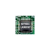
LAN8187-JT SMSC, LAN8187-JT Datasheet - Page 27

LAN8187-JT
Manufacturer Part Number
LAN8187-JT
Description
Ethernet ICs HiPerfrm Ethrnt PHY
Manufacturer
SMSC
Type
MII/RMII Ethernet Transceiverr
Datasheet
1.LAN8187-JT.pdf
(78 pages)
Specifications of LAN8187-JT
Ethernet Connection Type
10 Base-T, 100 Base-TX
Minimum Operating Temperature
0 C
Mounting Style
SMD/SMT
Product
Ethernet Transceivers
Number Of Transceivers
1
Standard Supported
802.3ab
Data Rate
10 MB, 100 MB
Supply Voltage (max)
3.3 V
Supply Voltage (min)
1.8 V
Supply Current (max)
39 mA, 81.6 mA
Maximum Operating Temperature
+ 70 C
Package / Case
TQFP-64
Lead Free Status / RoHS Status
Lead free / RoHS Compliant
Available stocks
Company
Part Number
Manufacturer
Quantity
Price
Company:
Part Number:
LAN8187-JT
Manufacturer:
Standard
Quantity:
1 040
Company:
Part Number:
LAN8187-JT
Manufacturer:
STM
Quantity:
5 362
Part Number:
LAN8187-JT
Manufacturer:
SMSC
Quantity:
20 000
±15kV ESD Protected MII/RMII 10/100 Ethernet Transceiver with HP Auto-MDIX & flexPWR
Datasheet
SMSC LAN8187/LAN8187i
4.7
Note 4.1
Note 4.2
The purpose of the Auto-negotiation function is to automatically configure the PHY to the optimum link
parameters based on the capabilities of its link partner. Auto-negotiation is a mechanism for
exchanging configuration information between two link-partners and automatically selecting the highest
performance mode of operation supported by both sides. Auto-negotiation is fully defined in clause 28
of the IEEE 802.3 specification.
Once auto-negotiation has completed, information about the resolved link can be passed back to the
controller via the Serial Management Interface (SMI). The results of the negotiation process are
reflected in the Speed Indication bits in register 31, as well as the Link Partner Ability Register
(Register 5).
The auto-negotiation protocol is a purely physical layer activity and proceeds independently of the MAC
controller.
The advertised capabilities of the PHY are stored in register 4 of the SMI registers. The default
advertised by the PHY is determined by user-defined on-chip signal options.
Auto-negotiation
SIGNAL NAME
COL/CRS_DV
CLKIN/XTAL1
RX_CLK
TX_CLK
RX_ER/
TX_ER/
RX_DV
TX_EN
TXD0
TXD1
RXD4
RXD0
RXD1
TXD2
TXD3
TXD4
RXD2
RXD3
CRS
In RMII mode, this pin needs to tied to VSS.
The RX_ER signal is optional on the RMII bus. This signal is required by the PHY, but it
is optional for the MAC. The MAC can choose to ignore or not use this signal.
Table 4.2 MII/RMII Signal Mapping
DATASHEET
27
CLKIN/XTAL1
MII MODE
®
RX_CLK
TX_CLK
RX_ER/
TX_ER/
RX_DV
TX_EN
Technology
RXD4/
RXD0
RXD1
RXD2
RXD3
TXD0
TXD1
TXD2
TXD3
TXD4
COL
CRS
RMII MODE
REF_CLK
CRS_DV
Note 4.2
Note 4.1
Note 4.1
RX_ER
TX_EN
RXD0
RXD1
TXD0
TXD1
Revision 1.7 (03-04-11)


