IRFPS40N50LPBF Vishay, IRFPS40N50LPBF Datasheet
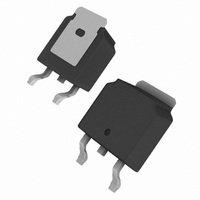
IRFPS40N50LPBF
Specifications of IRFPS40N50LPBF
Available stocks


Related parts for IRFPS40N50LPBF

IRFPS40N50LPBF Summary of contents
Page 1
... Higher Gate Voltage Threshold Offers Improved Noise Immunity D • Compliant to RoHS Directive 2002/95/EC APPLICATIONS • Zero Voltage Switching SMPS • Telecom and Server Power Supplies • Uninterruptible Power Supplies S • Motor Control Applications N-Channel MOSFET Super-247 IRFPS40N50LPbF SiHFPS40N50L-E3 IRFPS40N50L SiHFPS40N50L = 25 °C, unless otherwise noted ° 100 ° ...
Page 2
... IRFPS40N50L, SiHFPS40N50L Vishay Siliconix THERMAL RESISTANCE RATINGS PARAMETER a Maximum Junction-to-Ambient Case-to-Sink, Flat, Greased Surface a Maximum Junction-to-Case (Drain) Note measured at T approximately 90 ° SPECIFICATIONS ( °C, unless otherwise noted) J PARAMETER Static Drain-Source Breakdown Voltage V Temperature Coefficient DS Gate-Source Threshold Voltage Gate-Source Leakage Zero Gate Voltage Drain Current ...
Page 3
... J 0.1 0 Drain-to-Source Voltage (V) DS Fig Typical Output Characteristics Document Number: 91260 S11-0111-Rev. C, 07-Feb-11 IRFPS40N50L, SiHFPS40N50L 1000 100 4.5V ° 0.1 10 100 4.5V ° 10 100 Vishay Siliconix ° 150 ° 50V DS 20µs PULSE WIDTH Gate-to-Source Voltage (V) GS Fig Typical Transfer Characteristics 3 ...
Page 4
... IRFPS40N50L, SiHFPS40N50L Vishay Siliconix 1000000 0V MHZ C iss = SHORTED C rss = C gd 100000 C oss = 10000 Ciss 1000 Coss 100 Crss Drain-to-Source Voltage (V) Fig Typical Capacitance vs. Drain-to-Source Voltage 100 200 300 V DS, Drain-to-Source Voltage (V) Fig Typical Output Capacitance Stored Energy vs. V www.vishay.com 4 100 1000 Fig ...
Page 5
... Document Number: 91260 S11-0111-Rev. C, 07-Feb-11 IRFPS40N50L, SiHFPS40N50L Fig. 10a - Switching Time Test Circuit 125 150 10 % ° Fig. 10b - Switching Time Waveforms Notes: 1. Duty factor Peak 0.001 0. Rectangular Pulse Duration (sec) 1 Vishay Siliconix D.U. Pulse width ≤ 1 µs Duty factor ≤ 0 d(on) ...
Page 6
... IRFPS40N50L, SiHFPS40N50L Vishay Siliconix D.U. 0.01 Ω Fig. 12a - Unclamped Inductive Test Circuit Fig. 12b - Unclamped Inductive Waveforms 1000 OPERATION IN THIS AREA LIMITED BY R DS(on) 100 ° 150 C ° J Single Pulse 1 10 100 V , Drain-to-Source Voltage (V) DS Fig. 12c - Maximum Avalanche Energy vs. Drain Current www ...
Page 7
... Note Vishay Siliconix maintains worldwide manufacturing capability. Products may be manufactured at one of several qualified locations. Reliability data for Silicon Technology and Package Reliability represent a composite of all qualified locations. For related documents such as package/tape drawings, part marking, and reliability data, see www.vishay.com/ppg?91260. Document Number: 91260 S11-0111-Rev ...
Page 8
... Vishay product could result in personal injury or death. Customers using or selling Vishay products not expressly indicated for use in such applications their own risk and agree to fully indemnify and hold Vishay and its distributors harmless from and against any and all claims, liabilities, expenses and damages arising or resulting in connection with such use or sale, including attorneys fees, even if such claim alleges that Vishay or its distributor was negligent regarding the design or manufacture of the part ...