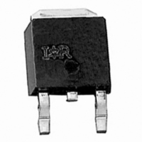
IRLR8503 International Rectifier, IRLR8503 Datasheet - Page 4

IRLR8503
Manufacturer Part Number
IRLR8503
Description
MOSFET N-CH 30V 44A DPAK
Manufacturer
International Rectifier
Series
HEXFET®r
Datasheet
1.IRLR8503.pdf
(9 pages)
Specifications of IRLR8503
Fet Type
MOSFET N-Channel, Metal Oxide
Fet Feature
Logic Level Gate
Rds On (max) @ Id, Vgs
16 mOhm @ 15A, 10V
Drain To Source Voltage (vdss)
30V
Current - Continuous Drain (id) @ 25° C
44A
Vgs(th) (max) @ Id
3V @ 250µA
Gate Charge (qg) @ Vgs
20nC @ 5V
Input Capacitance (ciss) @ Vds
1650pF @ 25V
Power - Max
62W
Mounting Type
Surface Mount
Package / Case
DPak, TO-252 (2 leads+tab), SC-63
Lead Free Status / RoHS Status
Contains lead / RoHS non-compliant
Other names
*IRLR8503
Available stocks
Company
Part Number
Manufacturer
Quantity
Price
Company:
Part Number:
IRLR8503
Manufacturer:
INTERNATIONAL RECTIFIER
Quantity:
30 000
Company:
Part Number:
IRLR8503PBF
Manufacturer:
INTERNATIONAL RECTIFIER
Quantity:
30 000
Company:
Part Number:
IRLR8503TR
Manufacturer:
IR
Quantity:
5 510
Company:
Part Number:
IRLR8503TRLPBF
Manufacturer:
INTERNATIONAL RECTIFIER
Quantity:
30 000
IRLR8503
Table 3 and Table 4 describes the event during the various charge segments and shows an approximation of losses during that
period.
4
The IRLR8103V and the IRLR8503 are suitable for
Synchronous Buck DC-DC Converters, and are optimized
for use in next generation CPU applications. The
IRLR8103V is primarily optimized for use as the low side
synchronous FET (Q2) with low R
immunity.The IRLR8503 is primarily optimized for use as
the high side control FET (Q2) with low cobmined Qsw and
R
IRLR8503 is also tested for Cdv/dt immunity, critical for
the low side socket. The typical configuration in which
these devices may be used in shown in Figure 7.
Conduction
Conduction
Gate Drive
Gate Drive
Switching
Switching
DS(on)
Output
Output
Loss
Loss
Loss
Loss
Loss
Loss
Loss
Loss
, but can also be used as a synchronous FET. The
Losses associated with MOSFET on time. I
duty cycle.
Losses associated with charging and discharging the gate of the MOSFET every
cycle. Use the Sync FET Q
Generally small enough to ignore except at light loads when the current reverses
in the output inductor. Under these conditions various light load power saving
techniques are employed by the control IC to maintain switching losses to a
negligible level.
Losses associated with the Q
turns on. They are caused by the synchronous FET, but are dissipated in the control
FET.
Losses associated with MOSFET on time. I
current and duty cycle.
Losses associated with charging and discharging the gate of the
MOSFET every cycle. Use the control FET Q
Losses during the drain voltage and drain current transitions for every full cycle.
Losses occur during the Q
Q
Losses associated with the Q
FET turns on. Losses are caused by both FETs, but are dissipated by the control
FET.
switch
.
DS(on)
and high CdV/dt
GS2
G
.
OSS
and Q
OSS
Table 4 – Synchronous FET Losses
of the device every cycle when the control FET
Table 3 – Control FET Losses
of the device every cycle when the control
Description
Description
GD
time period and can be simplified by using
RMS
RMS
G
.
is a function of load current and
is a function of load
or
1 x IRLR8103 or
Synchronous
2 x IRLR8503
FET (Q2)
Control FET (Q1)
IRLR8503
V
Figure 7 2 & 3-FET solution for
Synchronous Buck Topology.
P
P
P
P
P
P
P
P
P
P
IN
IN
QGS
QGD
SWITCH
OUTPUT
COND
SWITCH
OUTPUT
COND
=
=
Segment Losses
Segment Losses
2
≈
V
V
≈
=
G
G
=
V
≈
≈
www.irf.com
V
=
=
I
×
×
IN
RMS
I
IN
V
0
Q
Q
Q
Q
RMS
×
IN
×
OSS
G
OSS
G
2
2
I
2
L
I
×
2
L
×
×
×
×
I
×
×
L
R
ƒ
ƒ
×
×
Q
Q
Q
R
DSon
I
V
V
G
GD
I
I
GS
SW
G
IN
DS
G
IN
×
×
2
×
(
×
on
×
F
ƒ
ƒ
ƒ
)
ƒ


