MRF7S15100HR3 Freescale Semiconductor, MRF7S15100HR3 Datasheet
MRF7S15100HR3
Specifications of MRF7S15100HR3
Available stocks


Related parts for MRF7S15100HR3

MRF7S15100HR3 Summary of contents
Page 1
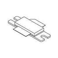
... MHz AVG CASE 465 - 06, STYLE 1 MRF7S1500HR3 CASE 465A - 06, STYLE 1 MRF7S1500HSR3 Symbol V DSS stg Symbol R θJC MRF7S15100HR3 MRF7S15100HSR3 Rev. 2, 6/2009 SINGLE W - CDMA LATERAL N - CHANNEL RF POWER MOSFETs NI - 780 NI - 780S Value Unit - 0.5, +65 Vdc - 6.0, +10 Vdc 32, +0 Vdc - 65 to +150 °C 150 °C 225 ° ...
Page 2
... W - CDMA, IQ Magnitude Clipping, Input Signal PAR = 7 0.01% Probability on CCDF. ACPR measured in 3.84 MHz Channel Bandwidth @ ±5 MHz Offset. Power Gain Drain Efficiency Output Peak - to - Average Ratio @ 0.01% Probability on CCDF Adjacent Channel Power Ratio Input Return Loss 1. Part internally matched both on input and output. MRF7S15100HR3 MRF7S15100HSR3 2 = 25°C unless otherwise noted) A Symbol I DSS I ...
Page 3
... Min Typ Max = 600 mA, 1470 - 1510 MHz Bandwidth — 100 — — 40 — — 70 — — 0.2 — — 4.5 — — 1.9 — — 23 — — 0.010 — — 0.007 — MRF7S15100HR3 MRF7S15100HSR3 Unit W MHz MHz dB ° ns ° dB/°C W/°C 3 ...
Page 4
... Z12 1.288″ x 0.144″ Microstrip Z13 1.288″ x 0.369″ Microstrip Z14 1.330″ x 0.112″ Microstrip Figure 1. MRF7S15100HR3(HSR3) Test Circuit Schematic Table 5. MRF7S15100HR3(HSR3) Test Circuit Component Designations and Values Part B1 Short Ferrite Bead C1, C6, C7 Chip Capacitors C2 0.5 pF Chip Capacitor ...
Page 5
... MRF7S15100H/HS Rev. 3 Figure 2. MRF7S15100HR3(HSR3) Test Circuit Component Layout RF Device Data Freescale Semiconductor C11 C9 C10 C6 C12 C13 C7 MRF7S15100HR3 MRF7S15100HSR3 5 ...
Page 6
... OUTPUT POWER (WATTS) CW out Figure 4. CW Power Gain versus Output Power −1 18 −2 17 −3 16 −4 15 −5 15 MRF7S15100HR3 MRF7S15100HSR3 6 TYPICAL CHARACTERISTICS Vdc (Avg.) DD out I = 600 mA, Single−Carrier W−CDMA DQ 3.84 MHz Channel Bandwidth, Input Signal PAR = 7 0.01% Probability on CCDF PARC IRL 1425 1450 1475 ...
Page 7
... MTTF calculator available at http://www.freescale.com/rf. Select Software & Tools/Development Tools/Calculators to access MTTF calculators by product. Figure 9. MTTF versus Junction Temperature 90 −18 25_C 75 −25 −30_C 25_C 60 −32 85_C − −46 15 −53 0 −60 100 200 0 −5 −10 −15 −20 −25 2250 230 250 = 32%. D MRF7S15100HR3 MRF7S15100HSR3 7 ...
Page 8
... Channel Bandwidth @ ±5 MHz Offset. 0.001 Input Signal PAR = 7 0.01% Probability on CCDF 0.0001 PEAK−TO−AVERAGE (dB) Figure 10. CCDF W - CDMA IQ Magnitude Clipping, Single - Carrier Test Signal MRF7S15100HR3 MRF7S15100HSR3 CDMA TEST SIGNAL 10 0 −10 −20 −30 −40 −50 −60 −ACPR in 3.84 MHz Integrated BW −70 − ...
Page 9
... Z = Test circuit impedance as measured from source gate to ground Test circuit impedance as measured load from drain to ground. Device Input Under Matching Test Network Z Z source load Output Matching Network MRF7S15100HR3 MRF7S15100HSR3 9 ...
Page 10
... ALTERNATIVE PEAK TUNE LOAD PULL CHARACTERISTICS NOTE: Load Pull Test Fixture Tuned for Peak P1dB Output Power @ 28 V MRF7S15100HR3 MRF7S15100HSR3 10 Ideal P3dB = 51.63 dBm (146 W) P1dB = 50.95 dBm (125 Vdc 600 mA, Pulsed μsec(on), 10% Duty Cycle 1500 MHz INPUT POWER (dBm) in Test Impedances per Compression Level ...
Page 11
... REF 0.127 REF F bbb 0.010 REF 0.254 REF ccc 0.015 REF 0.381 REF STYLE 1: PIN 1. DRAIN 2. GATE 5. SOURCE MRF7S15100HR3 MRF7S15100HSR3 MAX 34.16 9.91 4.32 12.83 1.14 0.15 1.70 5.33 19.96 20.00 3.51 9.53 9.52 11 ...
Page 12
... Fig. 10, CCDF W - CDMA IQ Magnitude Clipping, Single - Carrier Test Signal and Fig. 11, Single - Carrier W - CDMA Spectrum updated to show the undistorted input test signal • Added Electromigration MTTF Calculator and RF High Power Model availability to Product Documentation, Tools and Software MRF7S15100HR3 MRF7S15100HSR3 12 REVISION HISTORY Description ...
Page 13
... Freescale Semiconductor was negligent regarding the design or manufacture of the part. Freescalet and the Freescale logo are trademarks of Freescale Semiconductor, Inc. All other product or service names are the property of their respective owners. © Freescale Semiconductor, Inc. 2008-2009. All rights reserved. MRF7S15100HR3 MRF7S15100HSR3 13 ...