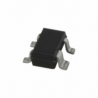
BFG10W/X,115 NXP Semiconductors, BFG10W/X,115 Datasheet - Page 6

BFG10W/X,115
Manufacturer Part Number
BFG10W/X,115
Description
TRANS NPN 10V 250MA SOT343N
Manufacturer
NXP Semiconductors
Datasheet
1.BFG10WX115.pdf
(11 pages)
Specifications of BFG10W/X,115
Package / Case
SOT-343N
Transistor Type
NPN
Voltage - Collector Emitter Breakdown (max)
10V
Frequency - Transition
1.9GHz
Power - Max
400mW
Dc Current Gain (hfe) (min) @ Ic, Vce
25 @ 50mA, 5V
Current - Collector (ic) (max)
250mA
Mounting Type
Surface Mount
Dc Current Gain Hfe Max
25 @ 50mA @ 5V
Mounting Style
SMD/SMT
Configuration
Single
Transistor Polarity
NPN
Collector- Emitter Voltage Vceo Max
10 V
Emitter- Base Voltage Vebo
2.5 V
Continuous Collector Current
0.25 A
Power Dissipation
400 mW
Maximum Operating Temperature
+ 175 C
Lead Free Status / RoHS Status
Lead free / RoHS Compliant
Gain
-
Noise Figure (db Typ @ F)
-
Lead Free Status / Rohs Status
Lead free / RoHS Compliant
Other names
934036590115
BFG10W/X T/R
BFG10W/X T/R
BFG10W/X T/R
BFG10W/X T/R
NXP Semiconductors
List of components (see Fig.6)
Notes
1. V
2. American Technical Ceramics type 100A or capacitor of same quality.
3. Resonant at 1900 MHz.
1995 Sep 22
handbook, full pagewidth
TR1
C1, C4, C7
C2
C3
C5
C6
C8
C9
L1
L4
L2, L3
R1
R2
R3
COMPONENT
UHF power transistor
PCB RT5880, thickness 0.79 mm.
BE
at 1 mA must be 0.65 V.
bias transistor, BC548 or equivalent
capacitor; notes 2 and 3
capacitor; note 2
capacitor; note 2
capacitor; note 2
capacitor; note 2
Philips multilayer capacitor
Philips capacitor
6 turns enamelled 0.7 mm copper wire
2 turns enamelled 0.7 mm copper wire
RF choke, Philips
metal film resistor
metal film resistor
metal film resistor
DESCRIPTION
C1
Fig.6 Class-AB test circuit at f = 900 MHz.
+V bias
R1
C2
TR1
C8
R2
C3
L1
L2
6
DUT
120 pF
6.8 pF
0.5 pF
1.2 pF
1.9 pF
1 nF, 10 V
1500 F, 10 V
275
100
10
note 1
C4
R3
VALUE
+V CC
C5
L4
L3
C6
length 3.5 mm
length 3 mm
DIMENSIONS
C9
MBG428
C7
Product specification
BFG10W/X
2222 032 14152
4312 020 36690
CATALOGUE No.


