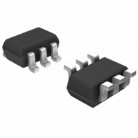
UPA808T-A CEL, UPA808T-A Datasheet - Page 2

UPA808T-A
Manufacturer Part Number
UPA808T-A
Description
TRANSISTOR NPN 11GHZ SOT363
Manufacturer
CEL
Datasheet
1.UPA808T-T1-A.pdf
(10 pages)
Specifications of UPA808T-A
Transistor Type
2 NPN (Dual)
Voltage - Collector Emitter Breakdown (max)
3V
Frequency - Transition
11GHz
Noise Figure (db Typ @ F)
1.3dB ~ 2dB @ 2GHz
Power - Max
180mW
Dc Current Gain (hfe) (min) @ Ic, Vce
70 @ 20mA, 2V
Current - Collector (ic) (max)
30mA
Mounting Type
Surface Mount
Package / Case
SC-70-6, SC-88, SOT-363
Dc Collector/base Gain Hfe Min
70
Dc Current Gain Hfe Max
140
Mounting Style
SMD/SMT
Configuration
Single
Transistor Polarity
NPN
Emitter- Base Voltage Vebo
2 V
Continuous Collector Current
0.03 A
Power Dissipation
90 mW
Lead Free Status / RoHS Status
Lead free / RoHS Compliant
Gain
-
Lead Free Status / RoHS Status
Lead free / RoHS Compliant, Lead free / RoHS Compliant
Note: 1.Operation in excess of any one of these parameters
TYPICAL PERFORMANCE CURVES
ABSOLUTE MAXIMUM RATINGS
UPA808T
SYMBOLS
V
V
V
T
P
CBO
CEO
EBO
T
STG
I
C
T
J
may result in permanent damage.
200
100
25
20
15
10
5
0
0
Collector to Base Voltage
Collector to Emitter Voltage
Emitter to Base Voltage
Collector Current
Total Power Dissipation
Junction Temperature
Storage Temperature
COLLECTOR TO EMITTER VOLTAGE
2 Elements in Total
Collector to Emitter Voltage, V
TOTAL POWER DISSIPATION vs.
PARAMETERS
Per Element
Ambient Temperature, T
COLLECTOR CURRENT vs.
AMBIENT TEMPERATURE
1.0
1 Die
2 Die
50
2.0
180 mW
90 mW
100
3.0
l
B
200 µA
180 µA
160 µA
140 µA
120 µA
100 µA
UNITS
= 20 µA
80 µA
60 µA
40 µA
A
mW
mW
mA
°C
°C
V
V
V
(°C)
CE
(V)
1
(T
-65 to +150
150
RATINGS
A
(T
= 25°C)
180
150
30
90
A
5
3
2
= 25˚C)
500
200
100
50
40
30
20
10
50
20
10
0
1
V
CE
Base to Emitter Voltage, V
BASE TO EMITTER VOLTAGE
= 2 V
COLLECTOR CURRENT vs.
2
COLLECTOR CURRENT
Collector Current, lc (mA)
DC CURRENT GAIN vs.
5
0.5
10
V
V
20
CE
CE
= 2 V
= 1 V
BE
50
(V)
100
1.0


