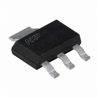
MCR08BT1,115 NXP Semiconductors, MCR08BT1,115 Datasheet

MCR08BT1,115
Specifications of MCR08BT1,115
MCR08BT1 T/R
MCR08BT1 T/R
Related parts for MCR08BT1,115
MCR08BT1,115 Summary of contents
Page 1
MCR08BT1 Thyristor; logic level Rev. 03 — 29 November 2004 SOT223 1. Product profile 1.1 General description Passivated, sensitive gate thyristor in a SOT223 plastic package. 1.2 Features Sensitive gate Surface mount package. 1.3 Applications General purpose switching and phase ...
Page 2
Philips Semiconductors 4. Limiting values Table 3: Limiting values In accordance with the Absolute Maximum Rating System (IEC 60134). Symbol Parameter repetitive peak off-state voltage DRM RRM I average on-state current T(AV) I RMS on-state current T(RMS) ...
Page 3
Philips Semiconductors 10 I TSM ( Hz. Fig 2. Non-repetitive peak on-state current as a function of the number of sinusoidal current cycles; maximum values TSM (A) 2 ...
Page 4
Philips Semiconductors 2.0 I T(RMS) (A) 1.5 1.0 0 Hz; T 112 C. sp Fig 4. RMS on-state current as a function of surge duration for sinusoidal currents; maximum values 5. Thermal ...
Page 5
Philips Semiconductors th(j-sp) (K/ Fig 6. Transient thermal impedance from junction to solder point as a function of pulse duration 6. Characteristics Table 5: Characteristics T = ...
Page 6
Philips Semiconductors 1.6 V GT(Tj) V GT(25 C) 1.2 0.8 0 Fig 7. Normalized gate trigger voltage as a function of junction temperature ( (1) (2) (3) 0 0.4 1.2 ...
Page 7
Philips Semiconductors 3 I H(Tj Fig 11. Normalized holding current as a function of junction temperature. 7. Package information Epoxy meets requirements of UL94 V-0 ...
Page 8
Philips Semiconductors 8. Package outline Plastic surface mounted package with increased heatsink; 4 leads DIMENSIONS (mm are the original dimensions) A UNIT 1.8 0.10 0.80 3.1 mm 1.5 0.01 0.60 ...
Page 9
Philips Semiconductors 9. Mounting 9.1 Mounting instructions Fig 14. SOT223: minimum footprint 9397 750 13513 Product data sheet 1.5 min 1.5 min (3 ) 1.5 min Dimensions in mm. Rev. 03 — 29 November 2004 MCR08BT1 Thyristor; logic level 3.8 ...
Page 10
Philips Semiconductors 10. Revision history Table 6: Revision history Document ID Release date MCR08BT1_3 20041129 • Modifications: The format of this data sheet has been redesigned to comply with the new presentation and information standard of Philips Semiconductors • Table ...
Page 11
Philips Semiconductors 11. Data sheet status [1] Level Data sheet status Product status I Objective data Development II Preliminary data Qualification III Product data Production [1] Please consult the most recently issued data sheet before initiating or completing a design. ...
Page 12
Philips Semiconductors 15. Contents 1 Product profi 1.1 General description ...


