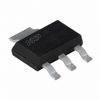
MCR08BT1,115 NXP Semiconductors, MCR08BT1,115 Datasheet - Page 6

MCR08BT1,115
Manufacturer Part Number
MCR08BT1,115
Description
THYRISTOR 0.8A 200V SOT223
Manufacturer
NXP Semiconductors
Type
SCRr
Datasheet
1.MCR08BT1115.pdf
(12 pages)
Specifications of MCR08BT1,115
Package / Case
SOT-223 (3 leads + Tab), SC-73, TO-261
Scr Type
Sensitive Gate
Voltage - Off State
200V
Voltage - Gate Trigger (vgt) (max)
800mV
Voltage - On State (vtm) (max)
1.7V
Current - On State (it (av)) (max)
500mA
Current - On State (it (rms)) (max)
800mA
Current - Gate Trigger (igt) (max)
200µA
Current - Hold (ih) (max)
5mA
Current - Off State (max)
100µA
Current - Non Rep. Surge 50, 60hz (itsm)
8A, 9A
Mounting Type
Surface Mount
Current - On State (it (rms) (max)
800mA
Breakover Current Ibo Max
9 A
Rated Repetitive Off-state Voltage Vdrm
200 V
Off-state Leakage Current @ Vdrm Idrm
0.1 mA
Forward Voltage Drop
1.7 V
Gate Trigger Voltage (vgt)
0.8 V
Maximum Gate Peak Inverse Voltage
5 V
Gate Trigger Current (igt)
0.2 mA
Holding Current (ih Max)
5 mA
Mounting Style
SMD/SMT
Repetitive Peak Off-state Volt
200V
Off-state Voltage
200V
Average On-state Current
500mA
Hold Current
5mA
Gate Trigger Current (max)
200uA
Gate Trigger Voltage (max)
800mV
Peak Reverse Gate Voltage
5V
Package Type
SC-73
Peak Repeat Off Current
100uA
Peak Surge On-state Current (max)
9A
On State Voltage(max)
1.7@1.2AV
Mounting
Surface Mount
Pin Count
3 +Tab
Operating Temp Range
-40C to 125C
Operating Temperature Classification
Automotive
Lead Free Status / RoHS Status
Lead free / RoHS Compliant
Lead Free Status / RoHS Status
Lead free / RoHS Compliant, Lead free / RoHS Compliant
Other names
934056931115
MCR08BT1 T/R
MCR08BT1 T/R
MCR08BT1 T/R
MCR08BT1 T/R
Philips Semiconductors
9397 750 13513
Product data sheet
Fig 7. Normalized gate trigger voltage as a function of
Fig 9. On-state current characteristics.
V
GT(25 C)
V
GT(Tj)
(1) T
(2) T
(3) T
(A)
I
T
1.6
1.2
0.8
0.4
5
4
3
2
1
0
junction temperature.
V
R
0.4
50
j
j
j
O
S
= 125 C; typical values.
= 125 C; maximum values.
= 25 C; maximum values.
= 0.27 .
= 1.0 V.
(1)
0
1.2
(2)
50
(3)
2
100
V
T
T
001aac109
001aac113
(V)
j
( C)
Rev. 03 — 29 November 2004
150
2.8
Fig 8. Normalized gate trigger current as a function of
Fig 10. Normalized latching current as a function of
I
GT(25 C)
I
L(25 C)
I
GT(Tj)
I
L(Tj)
3
2
1
0
3
2
1
0
junction temperature.
R
junction temperature.
50
50
GK
= 1 k .
0
0
© Koninklijke Philips Electronics N.V. 2004. All rights reserved.
50
50
MCR08BT1
Thyristor; logic level
100
100
001aac110
T
001aab503
T
j
j
( C)
( C)
150
150
6 of 12


