MAT02FHZ Analog Devices Inc, MAT02FHZ Datasheet - Page 10
MAT02FHZ
Manufacturer Part Number
MAT02FHZ
Description
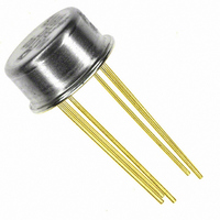
IC TRANS DUAL MATCHED NPN TO-78
Manufacturer
Analog Devices Inc
Datasheet
1.MAT02EH.pdf
(12 pages)
Specifications of MAT02FHZ
Transistor Type
2 NPN (Dual)
Current - Collector (ic) (max)
20mA
Voltage - Collector Emitter Breakdown (max)
40V
Vce Saturation (max) @ Ib, Ic
200mV @ 100µA, 1mA
Current - Collector Cutoff (max)
4nA
Power - Max
1.8W
Frequency - Transition
200MHz
Mounting Type
Through Hole
Package / Case
TO-78-6 Metal Can
Lead Free Status / RoHS Status
Lead free / RoHS Compliant
Dc Current Gain (hfe) (min) @ Ic, Vce
-


MAT02
Substituting in the voltage relationships and simplifying leads
to:
The factor “K” is a potentiometer position and varies from zero
to 1.0, so “m” ranges from R
Practical values are 125 Ω for R
values will provide an adjustment range of 0.2 to 5.0. A value
of 100 kΩ is recommended for the R
scale input range of 10 V. As with the one-quadrant
multiplier/divider circuit previously discussed, the V
V
The op amps should have the lowest possible input offsets. The
OP07 is recommended for most applications, although such
programmable micropower op amps as the OP193/OP293 offer
advantages in low-power or single-supply circuits. The micro-
power op amps also have very low input bias-current drift, an
important advantage in log/antilog circuits. External offset
nulling may be needed, particularly for applications requiring a
wide dynamic range. Frequency compensating capacitors, on
the order of 50 pF, may be required for A
A
assure stability.
Accuracy is limited at the higher input levels by bulk emitter
resistance, but this is much lower for the MAT02 than for other
transistor pairs. Accuracy at the lower signal levels primarily
depends on the op amp offsets. Accuracies of better than 1%
are readily achievable with this circuit configuration and can be
better than ± 0.1% over a limited operating range.
FAST LOGARITHMIC AMPLIFIER
The circuit of Figure 7 is a modification of a standard logarith-
mic amplifier configuration. Running the MAT02 at 2.5 mA
per side (full-scale) allows a fast response with wide dynamic
range. The circuit has a 7 decade current range, a 5 decade
voltage range, and is capable of 2.5 µs settling time to 1% with
a 1 V to 10 V step.
The output follows the equation:
The output is inverted with respect to the input, and is nomi-
nally –1 V/decade using the component values indicated.
Z
1
inputs must all be positive.
is likely to need a larger capacitor, typically 0.0047 µF, to
V
O
V
O
=
m =
=
R
R
3
R
R
R
O
+ R
1
2
B
V
R
+ 1 – K
2
Y
B
kT
(
q
+ KR
V
V
B
/(R
In
X
Z
B
and 500 Ω for R
V
)
A
m
A
V
R
REF
, where
+ R
IN
1
A
resistors assuming a full-
B
) to (R
2
and A
B
3
. Amplifier
+ R
A
; these
X
, V
A
)/R
Y
, and
B
(20)
(21)
.
–10–
LOW-NOISE
The MAT02 noise voltage is exceptionally low, only 1 nV/√Hz
at 10 Hz when operated over a collector current range of 1 mA
to 4 mA. A single-ended ×1000 amplifier that takes advantage of
this low MAT02 noise level is shown in Figure 8. In addition to
low noise, the amplifier has very low drift and high CMRR. An
OP184 is used for the second stage to obtain good speed with
minimal power consumption. Small-signal bandwidth is 4.0
MHz, slew rate is 2.4 V/µs, and total supply current is approxi-
mately 2.25 mA.
Figure 8. Low-Noise, Single-Ended × 1000 Amplifier
Figure 7. Fast Logarithmic Amplifier
1000 AMPLIFIER
REV. E
Related parts for MAT02FHZ
Image
Part Number
Description
Manufacturer
Datasheet
Request
R

Part Number:
Description:
±1.7g Dual-Axis IMEMS Accelerometer Evaluation Board
Manufacturer:
Analog Devices Inc
Datasheet:

Part Number:
Description:
Inertial Sensor Evaluation System
Manufacturer:
Analog Devices Inc
Datasheet:
Part Number:
Description:
Manufacturer:
Analog Devices Inc
Datasheet:
Part Number:
Description:
Manufacturer:
Analog Devices Inc
Datasheet:
Part Number:
Description:
Manufacturer:
Analog Devices Inc
Datasheet:
Part Number:
Description:
Manufacturer:
Analog Devices Inc
Datasheet:
Part Number:
Description:
Manufacturer:
Analog Devices Inc
Datasheet:
Part Number:
Description:
Manufacturer:
Analog Devices Inc
Datasheet:
Part Number:
Description:
Manufacturer:
Analog Devices Inc
Datasheet:
Part Number:
Description:
Manufacturer:
Analog Devices Inc
Datasheet:
Part Number:
Description:
Manufacturer:
Analog Devices Inc
Datasheet:
Part Number:
Description:
Manufacturer:
Analog Devices Inc
Datasheet:
Part Number:
Description:
Manufacturer:
Analog Devices Inc
Datasheet: