MAT02FHZ Analog Devices Inc, MAT02FHZ Datasheet - Page 11
MAT02FHZ
Manufacturer Part Number
MAT02FHZ
Description
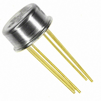
IC TRANS DUAL MATCHED NPN TO-78
Manufacturer
Analog Devices Inc
Datasheet
1.MAT02EH.pdf
(12 pages)
Specifications of MAT02FHZ
Transistor Type
2 NPN (Dual)
Current - Collector (ic) (max)
20mA
Voltage - Collector Emitter Breakdown (max)
40V
Vce Saturation (max) @ Ib, Ic
200mV @ 100µA, 1mA
Current - Collector Cutoff (max)
4nA
Power - Max
1.8W
Frequency - Transition
200MHz
Mounting Type
Through Hole
Package / Case
TO-78-6 Metal Can
Lead Free Status / RoHS Status
Lead free / RoHS Compliant
Dc Current Gain (hfe) (min) @ Ic, Vce
-


Transistors Q2 and Q3 form a 2 mA current source (0.65 V/
330 Ω ~ 2 mA). Each collector of Q1 operates at 1 mA. The
OP184 inputs are 3 V below the positive supply voltage (R
~ 3 V). Input stage gain is g
when operating at I
OP184 has a minimum open-loop gain of 500,000, total
open-loop gain for the composite amplifier is over 50 million.
Even at closed-loop gain of 1000, the gain error due to finite
open-loop gain will be negligible. The OP184 features excellent
symmetry of slew-rate and very linear gain. Signal distortion is
minimal.
Dynamic range of this amplifier is excellent; the OP184 has an
output voltage swing of ± 14.8 V with a ± 15 V supply.
Input characteristics are outstanding. The MAT02F has offset
voltage of less than 150 µV at 25°C and a maximum offset drift
of 1 µV/°C. Nulling the offset will further reduce offset drift.
This can be accomplished by slightly unbalancing the collector
load resistors. This adjustment will reduce the drift to less than
0.1 µV/°C.
REV. E
C
of 1 mA with R
m
R
L
, which is approximately 100
L
of 3 kΩ. Since the
L
I
C
–11–
Input bias current is relatively low due to the high current gain
of the MAT02. The minimum β of 400 at 1 mA for the
MAT02F implies an input bias current of approximately 2.5 µA.
This circuit should be used with signals having relatively low
source impedance. A high source impedance will degrade offset
and noise performance.
This circuit configuration provides exceptionally low input noise
voltage and low drift. Noise can be reduced even further by
raising the collector currents from 1 mA to 3 mA, but power
consumption is then increased.
MAT02
Related parts for MAT02FHZ
Image
Part Number
Description
Manufacturer
Datasheet
Request
R

Part Number:
Description:
±1.7g Dual-Axis IMEMS Accelerometer Evaluation Board
Manufacturer:
Analog Devices Inc
Datasheet:

Part Number:
Description:
Inertial Sensor Evaluation System
Manufacturer:
Analog Devices Inc
Datasheet:
Part Number:
Description:
Manufacturer:
Analog Devices Inc
Datasheet:
Part Number:
Description:
Manufacturer:
Analog Devices Inc
Datasheet:
Part Number:
Description:
Manufacturer:
Analog Devices Inc
Datasheet:
Part Number:
Description:
Manufacturer:
Analog Devices Inc
Datasheet:
Part Number:
Description:
Manufacturer:
Analog Devices Inc
Datasheet:
Part Number:
Description:
Manufacturer:
Analog Devices Inc
Datasheet:
Part Number:
Description:
Manufacturer:
Analog Devices Inc
Datasheet:
Part Number:
Description:
Manufacturer:
Analog Devices Inc
Datasheet:
Part Number:
Description:
Manufacturer:
Analog Devices Inc
Datasheet:
Part Number:
Description:
Manufacturer:
Analog Devices Inc
Datasheet:
Part Number:
Description:
Manufacturer:
Analog Devices Inc
Datasheet: