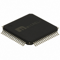
SY89221UHY Micrel Inc, SY89221UHY Datasheet - Page 9

SY89221UHY
Manufacturer Part Number
SY89221UHY
Description
2.5V/3.3V Integrated Divider + Fanout With 15 LVPECL Outputs Asn FSI Inputs (I Temp, )
Manufacturer
Micrel Inc
Series
Precision Edge®r
Type
Fanout Buffer (Distribution), Divider, Multiplexerr
Datasheet
1.SY89221UHY.pdf
(17 pages)
Specifications of SY89221UHY
Number Of Circuits
1
Ratio - Input:output
2:15
Differential - Input:output
Yes/Yes
Input
CML, LVDS, PECL
Output
LVPECL
Frequency - Max
2GHz
Voltage - Supply
2.375 V ~ 3.6 V
Operating Temperature
-40°C ~ 85°C
Mounting Type
Surface Mount
Package / Case
64-TQFP Exposed Pad, 64-eTQFP, 64-HTQFP, 64-VQFP
Frequency-max
2GHz
Lead Free Status / RoHS Status
Lead free / RoHS Compliant
Other names
576-1616
Available stocks
Company
Part Number
Manufacturer
Quantity
Price
Functional Description
Clock Select (CLK_SEL)
CLK_SEL is an asynchronous TTL/CMOS compatible
input that selects one of the two input signals. Internal
25kΩ pull-up resistor defaults the input to logic HIGH if
left open. Delay between the clock selection and
multiplexer selecting the correct input signal depends
on the divider settings. The delay varies due to the
asynchronous nature of the input. Input switching
threshold is V
Fail-Safe Input (FSI)
The input includes a special failsafe circuit to sense
the amplitude of the input signal and to latch the
outputs when there is no input signal present, or when
the amplitude of the input signal drops sufficiently
below
Maximum frequency of the SY89221U is limited by the
FSI function. Refer to Figure 2b.
Input Clock Failure Case
If the input clock fails to a floating, static, or extremely
low signal swing, the FSI function will eliminate a
metastable condition and guarantee a stable output
signal. No ringing and no undetermined state will
occur at the output under these conditions.
Please note that the FSI function will not prevent duty
cycle distortion in case of a slowly deteriorating (but
still toggling) input signal. Due to the FSI function, the
propagation delay will depend on rise and fall time of
the input signal and on its amplitude. Refer to “Typical
Operating Characteristics” for detailed information.
August 2007
100mV
CC
/2. Refer to Figure 2a.
PK
(200mV
PP
),
typically
30mV
PK
.
9
Master Reset (/MR)
/MR is a TTL/CMOS compatible input that resets the
output signals. Internal 25kΩ pull-up resistor defaults
the input to logic HIGH if left open. A LOW input to
/MR asynchronously sets the true outputs LOW and
complimentary outputs HIGH. The outputs will remain
in this state until /MR is forced HIGH. Input switching
threshold is V
Enable Outputs (EN)
EN is a synchronous TTL/CMOS compatible input that
enables/disables the outputs based on the input to
this pin. Internal 25kΩ pull-up resistor defaults the
input to logic HIGH if left open. A logic LOW input
causes
complementary outputs to go HIGH. It takes 2 to 6
input
enabled/disabled because the signals are going
through a series of flip-flops. Input switching threshold
is V
CC
/2. Refer to Figure 2d and 2e.
clock
the
CC
/2. Refer to Figure 2c.
true
cycles
hbwhelp@micrel.com
outputs
before
to
the
go
or (408) 955-1690
M9999-082407-C
outputs
LOW
and
are


