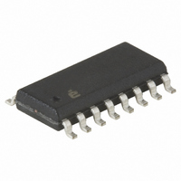
EL4584CS Intersil, EL4584CS Datasheet - Page 11

EL4584CS
Manufacturer Part Number
EL4584CS
Description
IC PLL VIDEO GP 36MHZ 16-SOIC
Manufacturer
Intersil
Type
Phase Lock Loop (PLL)r
Datasheet
1.EL4584CSZ.pdf
(15 pages)
Specifications of EL4584CS
Pll
Yes
Input
Clock
Output
CMOS, TTL
Number Of Circuits
1
Ratio - Input:output
3:1
Differential - Input:output
No/No
Frequency - Max
36MHz
Divider/multiplier
Yes/No
Voltage - Supply
5V
Operating Temperature
-40°C ~ 85°C
Mounting Type
Surface Mount
Package / Case
16-SOIC (3.9mm Width)
Frequency-max
36MHz
Number Of Elements
1
Supply Current
4mA
Operating Supply Voltage (typ)
5V
Operating Temp Range
-40C to 85C
Package Type
SOIC
Operating Temperature Classification
Industrial
Pin Count
16
Frequency
36MHz
Supply Voltage Range
5V
Digital Ic Case Style
SOIC
No. Of Pins
16
Operating Temperature Range
-40°C To +85°C
Peak Reflow Compatible (260 C)
No
Rohs Compliant
No
Lead Free Status / RoHS Status
Contains lead / RoHS non-compliant
Available stocks
Company
Part Number
Manufacturer
Quantity
Price
Company:
Part Number:
EL4584CS
Manufacturer:
Intersil
Quantity:
118
Part Number:
EL4584CS
Manufacturer:
INTERSIL
Quantity:
20 000
Company:
Part Number:
EL4584CSZ
Manufacturer:
Intersil
Quantity:
7
Company:
Part Number:
EL4584CSZ-T7
Manufacturer:
ROHM
Quantity:
2 375
Part Number:
EL4584CSZ-T7
Manufacturer:
EVERLIG
Quantity:
20 000
Lock Time
Let = R
lock time. Decreasing t decreases damping and speeds up
loop response, but increases overshoot and thus increases
the number of hunting oscillations before lock. Critical
damping (ζ = 1) occurs at minimum lock time. Because
decreased damping also decreases loop stability, it is
sometimes desirable to design slightly overdamped (ζ > 1),
trading lock time for increased stability.
C
C
R
FREQUENCY
TABLE 5. LC LOOP FILTER COMPONENTS (APPROXIMATE)
3
4
3
smaller, tθ (see “Timing Diagrams” on page 5) increases,
and if R
lock, |tθ| < 50 ns. C
frequency noise from the charge pump.
=
13.301
17.734
10.738
12.273
14.318
=
=
(MHz)
14.75
13.5
K
----------------------- -
C
------ -
----------------------- -
K
10
2Nζω
3
d
d
3
Nω
C
K
K
=
3
VCO
VCO
2
n
. As t increases, damping increases, but so does
2
0.0001µF
n
FIGURE 17. TYPICAL LOOP FILTER
increases, tθ decreases. For LDET to be low at
=
=
(
----------------------------------------------------- -
----------------------------------------------------- -
(
(kΩ)
4.77e 5
2 ( ) 910
100
100
100
100
100
100
100
4.77e 5
R
(
2
910
(
4
–
–
) 5000
is used mainly to attenuate high
(
) 1 ( ) 5000
) 6.05e6
) 6.05e6
(
(
11
(
(kΩ)
R
30
30
33
39
22
27
30
)
2
3
)
)
)
=
=
0.01µF
31.5kΩ
(µF)
0.01
0.01
0.01
0.01
0.01
0.01
0.01
C
3
(EQ. 10)
(EQ. 11)
0.001
0.001
0.001
0.001
0.001
0.001
0.001
(µF)
(EQ. 9)
C
4
EL4584
PCB Layout Considerations
It is highly recommended that power and ground planes be
used in layout. The oscillator and filter sections constitute a
feedback loop and thus care must be taken to avoid any
feedback signal influencing the oscillator except at the
control input. The entire oscillator/filter section should be
surrounded by copper ground to prevent unwanted
influences from nearby signals. Use separate paths for
analog and digital supplies, keeping the analog (oscillator
section) as short and free from spurious signals as possible.
Careful attention must be paid to correct bypassing. Keep
lead lengths short and place bypass capacitors as close to
the supply pins as possible. If laying out a PCB to use
discrete components for the VCO section, care must be
taken to avoid parasitic capacitance at the OSC pins 3 and
5, and FILTER out (pin 7). Remove ground and power plane
copper above and below these traces to avoid making a
capacitive connection to them. It is also recommended to
enclose the oscillator section within a shielded cage to
reduce external influences on the VCO, as they tend to be
very sensitive to “handwaving” influences, the LC variety
being more sensitive than crystal controlled oscillators. In
general, the higher the operating frequency, the more
important these considerations are. Self contained VCXO or
VCO modules are already mounted in a shielding cage and
therefore do not require as much consideration in layout.
Many crystal manufacturers publish informative literature
regarding use and layout of oscillators which should be
helpful.
The VCO and loop filter section of the EL4583, EL4584,
EL4585 demo board can be implemented in Figures 18, 19
and 20.
FREQUENCY
TABLE 6. XTAL LOOP FILTER COMPONENTS
13.301
17.734
10.738
12.273
14.318
(MHz)
14.75
13.5
(APPROXIMATE)
(kΩ)
100
100
100
100
100
100
100
R
2
(MΩ)
4.3
4.3
4.3
4.3
4.3
4.3
4.3
R
3
(pF)
C
68
68
68
68
68
68
68
3
May 9, 2008
(pF)
6.8
6.8
6.8
6.8
6.8
6.8
6.8
C
FN7174.3
4


