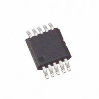
ISL1209IU10Z Intersil, ISL1209IU10Z Datasheet - Page 10

ISL1209IU10Z
Manufacturer Part Number
ISL1209IU10Z
Description
IC RTC LP BATT BACK SRAM 10MSOP
Manufacturer
Intersil
Type
Clock/Calendar/NVSRAMr
Datasheet
1.ISL1209IU10Z-TK.pdf
(24 pages)
Specifications of ISL1209IU10Z
Memory Size
2B
Time Format
HH:MM:SS (12/24 hr)
Date Format
YY-MM-DD-dd
Interface
I²C, 2-Wire Serial
Voltage - Supply
2.7 V ~ 5.5 V
Operating Temperature
-40°C ~ 85°C
Mounting Type
Surface Mount
Package / Case
10-MSOP, Micro10™, 10-uMAX, 10-uSOP
Lead Free Status / RoHS Status
Lead free / RoHS Compliant
Available stocks
Company
Part Number
Manufacturer
Quantity
Price
Company:
Part Number:
ISL1209IU10Z-TK
Manufacturer:
Intersil
Quantity:
47 631
Company:
Part Number:
ISL1209IU10Z-TK
Manufacturer:
Intersil
Quantity:
625
Users have the option to connect EVIN (see EVINEB bit) to
an internal pull up current source that operates at 1
(always on mode). User selectable event sampling modes
are also available which will effectively reduce power
consumption with 1/4-Hz, 1-Hz and 2-Hz sample detection
rates. The EVIN input is pulsed ON/OFF when in sampling
mode for power savings advantages (See tables below).
The EVIN also has a user selectable time based hysteresis
filter (see EHYS bits) to implement switch de-bouncing
during an event detection. The EVIN signal must be high for
the duration of the selected time period. The time periods
available are 0 times delay (no time based hysteresis) to
3.9ms, 15.625ms or 31.25ms (see Table 1, 2, 3, and 4).
Real Time Clock Operation
The Real Time Clock (RTC) uses an external 32.768kHz
quartz crystal to maintain an accurate internal representation
of second, minute, hour, day of week, date, month, and year.
The RTC also has leap-year correction. The clock also
corrects for months having fewer than 31 days and has a bit
that controls 24 hour or AM/PM format. When the ISL1209
powers up after the loss of both V
not begin incrementing until at least one byte is written to the
clock register.
TABLE 3. ∆I
TABLE 4. ∆I
TABLE 2. ∆I
TABLE 1. ∆I
1/4Hz
1/4Hz
1/4Hz
1/4Hz
f
f
f
f
1Hz
2Hz
1Hz
2Hz
1Hz
2Hz
1Hz
2Hz
SMP
SMP
SMP
SMP
DD
DD
DD
DD
(V
(V
(V
DD
DD
(V
DD
10
DD
=5.0V, t
=3.0V, t
=5.0V, t
=3V, t
DD
HYS
HYS
and V
HYS
HYS
=15.625ms)
=15.625ms)
DELTA I
DELTA I
DELTA I
DELTA I
=3.9ms)
263.3nA
526.5nA
656.3nA
=3.9ms)
20.5nA
65.8nA
1.05µA
164nA
328nA
264nA
BAT
2.1µA
82nA
82nA
, the clock will
DD
DD
DD
DD
µA
ISL1209
Accuracy of the Real Time Clock
The accuracy of the Real Time Clock depends on the
frequency of the quartz crystal that is used as the time base
for the RTC. Since the resonant frequency of a crystal is
temperature dependent, the RTC performance will also be
dependent upon temperature. The frequency deviation of
the crystal is a function of the turnover temperature of the
crystal from the crystal’s nominal frequency. For example, a
~20ppm frequency deviation translates into an accuracy of
~1 minute per month. These parameters are available from
the crystal manufacturer. The ISL1209 provides on-chip
crystal compensation networks to adjust load capacitance to
tune oscillator frequency from -94ppm to +140ppm. For
more detailed information see the Application Section.
Single Event and Interrupt
The alarm mode is enabled via the ALME bit. Choosing
single event or interrupt alarm mode is selected via the IM
bit. Note that when the frequency output function is enabled,
the alarm function is disabled.
The standard alarm allows for alarms of time, date, day of
the week, month, and year. When a time alarm occurs in
single event mode, an IRQ pin will be pulled low and the
alarm status bit (ALM) will be set to “1”.
The pulsed interrupt mode allows for repetitive or recurring
alarm functionality. Hence, once the alarm is set, the device
will continue to alarm for each occurring match of the alarm
and present time. Thus, it will alarm as often as every minute
(if only the nth second is set) or as infrequently as once a
year (if at least the nth month is set). During pulsed interrupt
mode, the IRQ pin will be pulled low for 250ms and the alarm
status bit (ALM) will be set to “1”.
The ALM bit can be reset by the user or cleared
automatically using the auto reset mode (see ARST bit).
The alarm function can be enabled/disabled during battery
backup mode using the FOBATB bit. For more information
on the alarm, please see the Alarm Registers Description.
Frequency Output Mode
The ISL1209 has the option to provide a frequency output
signal using the IRQ/F
is set by using the FO bits to select 15 possible output
frequency values from 0 to 32kHz. The frequency output can
be enabled/disabled during battery backup mode using the
FOBATB bit.
General Purpose User SRAM
The ISL1209 provides 2 bytes of user SRAM. The SRAM will
continue to operate in battery backup mode. However, it
should be noted that the I
backup mode.
OUT
2
C bus is disabled in battery
pin. The frequency output mode
October 17, 2006
FN6109.4


