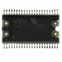
M48T37Y-70MH1E STMicroelectronics, M48T37Y-70MH1E Datasheet - Page 16

M48T37Y-70MH1E
Manufacturer Part Number
M48T37Y-70MH1E
Description
IC TIMEKPR NVRAM 256KBIT5V 44SOH
Manufacturer
STMicroelectronics
Series
Timekeeper®r
Type
Clock/Calendar/NVSRAMr
Specifications of M48T37Y-70MH1E
Memory Size
256K (32K x 8)
Time Format
HH:MM:SS (24 hr)
Date Format
YY-MM-DD-dd
Interface
Parallel
Voltage - Supply
4.5 V ~ 5.5 V
Operating Temperature
0°C ~ 70°C
Mounting Type
Surface Mount
Package / Case
44-SOH
Bus Type
Parallel
User Ram
32KB
Operating Supply Voltage (typ)
5V
Package Type
SOH
Operating Supply Voltage (max)
5.5V
Operating Supply Voltage (min)
4.5V
Operating Temperature Classification
Commercial
Operating Temperature (max)
70C
Operating Temperature (min)
0C
Pin Count
44
Mounting
Surface Mount
Memory Configuration
32K X 8
Nvram Features
RTC
Interface Type
Parallel
Access Time
70ns
Supply Voltage Range
4.5V To 5.5V
Memory Case Style
SOIC
No. Of Pins
44
Rohs Compliant
Yes
Lead Free Status / RoHS Status
Lead free / RoHS Compliant
Other names
497-2854-5
M48T37Y-70MH1
M48T37Y-70MH1
Available stocks
Company
Part Number
Manufacturer
Quantity
Price
Company:
Part Number:
M48T37Y-70MH1E
Manufacturer:
ST
Quantity:
936
M48T37Y, M48T37V
The second approach is better suited to a manu-
facturing environment, and involves the use of the
IRQ/FT pin. The pin will toggle at 512 Hz when the
Stop Bit (ST, D7 of 7FF9h) is '0' the Frequency
Test Bit (FT, D6 of 7FFCh) is '1,' the Alarm Flag
Enable Bit (AFE, D7 of 7FF6h) is '0,' and the
Watchdog Steering Bit (WDS, D7 of 7FF7h) is '1'
or the Watchdog Register is reset (7FF7h=0).
Any deviation from 512 Hz indicates the degree
and direction of oscillator frequency shift at the test
temperature. For example, a reading of 512.01024
Hz would indicate a +20 PPM oscillator frequency
error, requiring a –10(WR001010) to be loaded
into the Calibration Byte for correction.
Note: Setting or changing the Calibration Byte
does not affect the Frequency Test output fre-
quency.
The IRQ/FT pin is an open drain output which re-
quires a pull-up resistor for proper operation. A
500-10k
control the rise time. The FT Bit is cleared on pow-
er-down.
For more information on calibration, see the Appli-
cation Note AN934, “TIMEKEEPER Calibration.”
Watchdog Timer
The watchdog timer can be used to detect an out-
of-control microprocessor. The user programs the
watchdog timer by setting the desired amount of
time-out into the eight-bit Watchdog Register, ad-
dress 7FF7h. The five bits (BMB4-BMB0) that
store a binary multiplier and the two lower order
bits (RB1-RB0) select the resolution, where
00 =
and 11 = 4 seconds. The amount of time-out is
then determined to be the multiplication of the five-
bit multiplier value with the resolution. (For exam-
ple: writing 00001110 in the Watchdog Register =
3x1, or 3 seconds).
Note: Accuracy of timer is within ± the selected
resolution.
If the processor does not reset the timer within the
specified period, the M48T37Y/V sets the Watch-
dog Flag (WDF) and generates a watchdog inter-
16/29
1
/
16
second, 01 =
resistor is recommended in order to
1
/
4
second, 10 = 1 second,
rupt or a microprocessor reset. WDF is reset by
reading the Flags Register (Address 7FF0h).
Note: User must transition address (or toggle chip
enable) to see Flag Bit change.
Reset will not occur unless the addresses are sta-
ble at the flag location for at least 15ns while the
device is in the READ Mode as shown in
10., page
The most significant bit of the Watchdog Register
is the Watchdog Steering Bit. When set to a '0,' the
watchdog will activate the IRQ/FT pin when timed-
out. When WDS is set to a '1,' the watchdog will
output a negative pulse on the RST pin for a dura-
tion of t
AFE Bit, and ABE Bit will reset to a '0' at the end of
a Watchdog time-out when the WDS bit is set to a
'1.'
The watchdog timer resets when the microproces-
sor performs a re-write of the Watchdog Register
or an edge transition (low to high / high to low) on
the WDI pin occurs. The time-out period then
starts over.
The watchdog timer is disabled by writing a value
of 00000000 to the eight bits in the Watchdog Reg-
ister. Should the watchdog timer time-out, a value
of 00h needs to be written to the Watchdog Regis-
ter in order to clear the IRQ/FT pin.
The watchdog function is automatically disabled
upon power-down and the Watchdog Register is
cleared. If the watchdog function is set to output to
the IRQ/FT pin and the frequency test function is
activated, the watchdog or alarm function prevails
and the frequency test function is denied. The WDI
pin should be connected to V
Power-on Reset
The M48T37Y/V continuously monitors V
When V
the RST pulls low (open drain) and remains low on
power-up for t
valid for all V
open drain output and an appropriate resistor to
V
Figure 14., page
CC
should be chosen to control rise time (see
REC
CC
18.
falls to the power fail detect trip point,
. The Watchdog Register, the FT Bit,
REC
CC
23).
conditions. The RST pin is an
after V
CC
passes V
SS
if not used.
PFD
. RST is
Figure
CC
.


