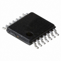
PCA2125TS/1,112 NXP Semiconductors, PCA2125TS/1,112 Datasheet - Page 6

PCA2125TS/1,112
Manufacturer Part Number
PCA2125TS/1,112
Description
IC CMOS RTC/CALENDAR 14-TSSOP
Manufacturer
NXP Semiconductors
Type
Clock/Calendar/Alarmr
Datasheet
1.PCA2125TS1112.pdf
(36 pages)
Specifications of PCA2125TS/1,112
Package / Case
14-TSSOP
Time Format
HH:MM:SS (12/24 hr)
Date Format
YY-MM-DD-dd
Interface
SPI, 3-Wire Serial
Voltage - Supply
1.3 V ~ 5.5 V
Operating Temperature
-40°C ~ 125°C
Mounting Type
Surface Mount
Function
Clock, Calendar
Supply Voltage (max)
5.5 V
Supply Voltage (min)
1.3 V
Maximum Operating Temperature
+ 125 C
Minimum Operating Temperature
- 40 C
Mounting Style
SMD/SMT
Rtc Bus Interface
Serial
Lead Free Status / RoHS Status
Lead free / RoHS Compliant
For Use With
OM6292 - DEMO BOARD PCA2125 RTC
Memory Size
-
Lead Free Status / RoHS Status
Lead free / RoHS Compliant, Lead free / RoHS Compliant
Other names
935283386112
PCA2125TS/1
PCA2125TS/1
PCA2125TS/1
PCA2125TS/1
NXP Semiconductors
PCA2125_1
Product data sheet
8.2.1 Power-on reset override
Table 5.
Bits labeled ‘-’ are not implemented and will return a ‘0’ when read. Bits labeled ‘X’ are undefined at
power-up and unchanged by subsequent resets.
After reset, the following mode is entered:
The SPI-bus is initialized whenever the chip enable pin CE is inactive (LOW).
The Power-On Reset (POR) duration is directly related to the crystal oscillator start-up
time. Due to the long start-up times experienced by these types of circuits, a mechanism
has been built in to disable the POR and hence speed up the on-board test of the device.
The setting of this mode requires that bit POR_OVRD be set to logic 1 and that the signals
at the SPI-bus pins SDI and CE are toggled as illustrated in
required minimums.
Once the override mode has been entered, the device immediately stops being reset and
set-up operation can commence i.e. entry into the external clock test mode via the
SPI-bus access. The override mode can be cleared by writing a logic 0 to bit POR_OVRD.
Bit POR_OVRD must be set to logic 1 before a re-entry into the override mode is possible.
Setting bit POR_OVRD to logic 0 during normal operation has no effect except to prevent
accidental entry into the POR override mode. This is the recommended setting.
Address
07h
08h
09h
0Ah
0Bh
0Ch
0Dh
0Eh
0Fh
Fig 5.
•
•
•
32.768 kHz on pin CLKOUT active
Power-on reset override available to be set
24 hour mode is selected
override
reset
SDI
CE
POR override sequence
Register reset value
Register name
Months
Years
Minute_alarm
Hour_alarm
Day_alarm
Weekday_alarm
CLKOUT_control
Timer_control
Countdown_timer
minimum 500 ns
Rev. 01 — 28 July 2008
minimum 500 ns
…continued
X
X
7
1
1
1
1
0
-
-
X
X
X
6
-
-
-
-
-
-
X
X
X
X
X
5
-
-
-
-
X
X
X
X
X
X
minimum 2000 ns
4
POR override set at this time
-
-
-
Bit
SPI Real-time clock/calendar
Figure
X
X
X
X
X
X
3
-
-
-
5. All timings are
PCA2125
X
X
X
X
X
X
X
2
0
-
© NXP B.V. 2008. All rights reserved.
001aaf900
X
X
X
X
X
X
X
1
0
1
6 of 36
X
X
X
X
X
X
X
0
0
1


