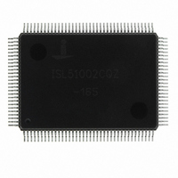
ISL51002CQZ-165 Intersil, ISL51002CQZ-165 Datasheet - Page 13

ISL51002CQZ-165
Manufacturer Part Number
ISL51002CQZ-165
Description
IC FRONT END 10BIT VID 128-MQFP
Manufacturer
Intersil
Datasheet
1.ISL51002CQZ-165.pdf
(32 pages)
Specifications of ISL51002CQZ-165
Number Of Bits
10
Number Of Channels
3
Power (watts)
1.2W
Voltage - Supply, Analog
1.8V, 3.3V
Voltage - Supply, Digital
1.8V, 3.3V
Package / Case
128-MQFP, 128-PQFP
Rohs Compliant
Yes
Lead Free Status / RoHS Status
Lead free / RoHS Compliant
Available stocks
Company
Part Number
Manufacturer
Quantity
Price
Part Number:
ISL51002CQZ-165
Manufacturer:
INTERSIL
Quantity:
20 000
Register Listing
CONFIGURATION REGISTERS
0x10
0x11
0x12
0x13
0x14
0x15
0x16
0x17
0x18
ADDRESS
Input Configuration,
(0x00)
Sync Source Selection,
(0x00)
Red Gain MSB, (0x55)
Red Gain LSB, (0x00)
Green Gain MSB, (0x55)
Green Gain LSB, (0x00)
Blue Gain MSB, (0x55)
Blue Gain LSB, (0x00)
Red Offset MSB, (0x80)
(DEFAULT VALUE)
REGISTER
(Continued)
13
BITS
1:0
7:0
5:0
7:6
7:0
5:0
7:6
7:0
5:0
7:6
7:0
2
3
4
5
6
7
0
1
2
Input Channel Select
Differential Mode Enable
DC Coupled Input Enable
RGB YUV
High Voltage Enable
EXT Clamp SEL
EXT Clamp POL
Sync Select
HSYNC Source
VSYNC Source
Red Gain MSB
N/A
Red Gain LSB
Green Gain MSB
N/A
Green Gain LSB
Blue Gain MSB
N/A
Blue Gain LSB
Red Offset MSB
FUNCTION NAME
ISL51002
Sets video muxes as well as HSYNC, VSYNC, and SOG input
muxes.
0: CH0
1: CH1
2: CH2 (single-ended mode only)
3: CH3 (single-ended mode only)
0: Single-Ended Mode
1: Differential Mode
0: AC-coupled Inputs
1: DC-coupled Inputs
0: RGB inputs (Clamp DAC = 300mV for R, G, B, half scale
1: YPbPr inputs (Clamp DAC = 600mV for R and B, 300mV for
0: Normal Input Range
1: Expanded 2.2V Input Range
0: Internal CLAMP generation
1: External CLAMP source
0: Active high external CLAMP
1: Active low external CLAMP
0: Automatic (HSYNC, VSYNC sources selected based on
1: Manual (bits 1and 2 determine HSYNC and VSYNC source)
0: HSYNC input pin
1: SOG
0: VSYNC input pin
1: Sync Separator output
Red channel gain, where: gain (V/V) = 0.5 + [9:0]/682
MSB/LSB
0x00 00: gain = 0.5 V/V (1.4V
0x55 00: gain = 1.0 V/V (0.7V
0xFF C0: gain = 2.0 V/V (0.35V
2 LSBs of 10-bit gain word
See Red Gain
See Red Gain
See Red Gain
See Red Gain
ABLC off: upper 8-bits to Red offset DAC
ABLC enabled: Red digital offset
0x00 00 = min DAC value or -0x80 digital offset
0x80 00 = mid DAC value or 0x00 digital offset,
0xFF C0= max DAC value or +0x7F digital offset
analog shift for R, G, and B, base ABLC target code = 0x00
for R, G, and B)
G, half scale analog shift for G channel only, base ABLC
target code = 0x00 for G, = 0x80 for R and B)
sync activity. Multiplexer settings chosen are displayed in
the Input Characteristics register.)
DESCRIPTION
P-P
P-P
P-P
input = full range of ADC)
input = full range of ADC)
input = full range of ADC)
September 19, 2007
FN6164.2


