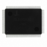
ISL51002CQZ-165 Intersil, ISL51002CQZ-165 Datasheet - Page 32

ISL51002CQZ-165
Manufacturer Part Number
ISL51002CQZ-165
Description
IC FRONT END 10BIT VID 128-MQFP
Manufacturer
Intersil
Datasheet
1.ISL51002CQZ-165.pdf
(32 pages)
Specifications of ISL51002CQZ-165
Number Of Bits
10
Number Of Channels
3
Power (watts)
1.2W
Voltage - Supply, Analog
1.8V, 3.3V
Voltage - Supply, Digital
1.8V, 3.3V
Package / Case
128-MQFP, 128-PQFP
Rohs Compliant
Yes
Lead Free Status / RoHS Status
Lead free / RoHS Compliant
Available stocks
Company
Part Number
Manufacturer
Quantity
Price
Part Number:
ISL51002CQZ-165
Manufacturer:
INTERSIL
Quantity:
20 000
PIN 1 ID
Metric Plastic Quad Flatpack Packages (MQFP)
Intersil products are sold by description only. Intersil Corporation reserves the right to make changes in circuit design, software and/or specifications at any time without
notice. Accordingly, the reader is cautioned to verify that data sheets are current before placing orders. Information furnished by Intersil is believed to be accurate and
reliable. However, no responsibility is assumed by Intersil or its subsidiaries for its use; nor for any infringements of patents or other rights of third parties which may result
from its use. No license is granted by implication or otherwise under any patent or patent rights of Intersil or its subsidiaries.
C0.600x0.350
SEATING
PLANE
(4X)
1
A
128
All Intersil U.S. products are manufactured, assembled and tested utilizing ISO9000 quality systems.
A2
A1
12.500 REF
Intersil Corporation’s quality certifications can be viewed at www.intersil.com/design/quality
C
For information regarding Intersil Corporation and its products, see www.intersil.com
D1
D
DROP IN HEAT SPREADER
4 STAND POINTS EXPOSED
DETAIL Y
32
b
e
1
ddd
M
A
A
0.200 MIN
C
ALL
AROUND
E1
R0.25 TYP
ALL AROUND
α
0° MIN
L1
E
T
13.870 ±0.100
1 SECTION A-A
14.000 ±0.100
L
R0.13 MIN
0.13~0.30
(D1)
T
b1
b
GAUGE
PLANE
0.25 BASE
ISL51002
T1
Y
MDP0055
14x20mm 128 LEAD MQFP (WITH AND WITHOUT HEAT
SPREADER) 3.2mm FOOTPRINT
NOTES:
1. General tolerance: Distance ±0.100, Angle +2.5°.
2.
3. All molded body sharp corner RADII unless otherwise specified
4. Package/Leadframe misalignment (X, Y): Max. 0.127
5. Top/Bottom misalignment (X, Y): Max. 0.127
6. Drawing does not include plastic or metal protrusion or cutting
7.
SYMBOL
pin 1 marking (Ra 0.8~2.0um).
(Max RO.200).
burr.
ddd
ccc
A1
A2
D1
E1
b1
L1
T1
1
2
A
α
D
E
b
e
L
T
Compliant to JEDEC MS-022.
Matte finish on package body surface except ejection and
( MILLIMETERS)
17.200 ±0.250
14.000 ±0.100
23.200 ±0.250
20.000 ±0.100
DIMENSIONS
2.750 ±0.250
0.220 ±0.050
0.200 ±0.030
0.880 ±0.150
0.170 ±0.060
0.152 ±0.040
0.250~0.500
0.500 Base
1.600 Ref.
Max 3.40
0°~7°
0.100
0.100
Overall height
Standoff
Package thickness
Foot angle
Lead width
Lead base metal width
Lead tip to tip
Package length
Lead tip to tip
Package width
Lead pitch
Foot length
Lead length
Frame thickness
Frame base metal thickness
Foot coplanarity
Foot position
REMARKS
1
September 19, 2007
1
Rev. 2 2/07
1
FN6164.2
1


