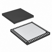
MAX19713ETN+ Maxim Integrated Products, MAX19713ETN+ Datasheet - Page 31

MAX19713ETN+
Manufacturer Part Number
MAX19713ETN+
Description
IC ANLG FRONT END 45MSPS 56-TQFN
Manufacturer
Maxim Integrated Products
Datasheet
1.MAX19713ETN.pdf
(37 pages)
Specifications of MAX19713ETN+
Number Of Bits
10
Number Of Channels
2
Power (watts)
91.8mW
Voltage - Supply, Analog
3V
Voltage - Supply, Digital
3V
Package / Case
56-TQFN Exposed Pad
Lead Free Status / RoHS Status
Lead free / RoHS Compliant
capacitor in parallel with a 2.2µF capacitor. Bypass REFP,
REFN, and COM each to GND with a 0.33µF ceramic
capacitor. Bypass REFIN to GND with a 0.1µF capacitor.
Multilayer boards with separated ground and power
planes yield the highest level of signal integrity. Use a
split ground plane arranged to match the physical loca-
tion of the analog ground (GND) and the digital output-
driver ground (OGND) on the device package. Connect
the MAX19713 exposed backside paddle to the GND
plane. Join the two ground planes at a single point so
the noisy digital ground currents do not interfere with
the analog ground plane. The ideal location for this
connection can be determined experimentally at a
point along the gap between the two ground planes.
Make this connection with a low-value, surface-mount
resistor (1Ω to 5Ω), a ferrite bead, or a direct short.
Alternatively, all ground pins could share the same
ground plane, if the ground plane is sufficiently isolated
Figure 12. Rx ADC DC-Coupled Differential Drive
______________________________________________________________________________________
R1
600Ω
R2
600Ω
R3
600Ω
600Ω
600Ω
600Ω
600Ω
R10
R4
R6
R8
10-Bit, 45Msps, Full-Duplex
600Ω
600Ω
600Ω
600Ω
R11
R7
R9
R5
from any noisy digital system’s ground plane (e.g.,
downstream output buffer or DSP ground plane).
Route high-speed digital signal traces away from sensi-
tive analog traces. Make sure to isolate the analog
input lines to each respective converter to minimize
channel-to-channel crosstalk. Keep all signal lines short
and free of 90° turns.
Integral nonlinearity is the deviation of the values on an
actual transfer function from a straight line. This straight
line can be either a best-straight-line fit or a line drawn
between the end points of the transfer function, once
offset and gain errors have been nullified. The static lin-
earity parameters for the device are measured using
the best-straight-line fit (DAC Figure 14a).
ADC and DAC Static Parameter Definitions
Dynamic Parameter Definitions
R
22Ω
R
22Ω
ISO
ISO
Analog Front-End
C
5pF
C
5pF
IN
IN
IAN
COM
IAP
Integral Nonlinearity (INL)
MAX19713
31


