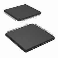
ADC083000CIYB/NOPB National Semiconductor, ADC083000CIYB/NOPB Datasheet - Page 26

ADC083000CIYB/NOPB
Manufacturer Part Number
ADC083000CIYB/NOPB
Description
IC ADC 8BIT 3GSPS LP 128-LQFP
Manufacturer
National Semiconductor
Series
PowerWise®r
Datasheet
1.ADC083000CIYBNOPB.pdf
(40 pages)
Specifications of ADC083000CIYB/NOPB
Number Of Bits
8
Sampling Rate (per Second)
3G
Data Interface
Serial
Number Of Converters
2
Power Dissipation (max)
2.3W
Voltage Supply Source
Single Supply
Operating Temperature
-40°C ~ 85°C
Mounting Type
Surface Mount
Package / Case
128-LQFP Exposed Pad
Lead Free Status / RoHS Status
Lead free / RoHS Compliant
Other names
*ADC083000CIYB
*ADC083000CIYB/NOPB
ADC083000CIYB
*ADC083000CIYB/NOPB
ADC083000CIYB
Available stocks
Company
Part Number
Manufacturer
Quantity
Price
Company:
Part Number:
ADC083000CIYB/NOPB
Manufacturer:
IPS
Quantity:
2 300
Part Number:
ADC083000CIYB/NOPB
Manufacturer:
TI/德州仪器
Quantity:
20 000
www.national.com
voltage can be increased to 1.150V by tying the V
V
IMPORTANT NOTE: Tying the V
crease the differential LVDS output voltage (V
40mV.
1.1.7 Power Down
The ADC083000 is in the active state when the Power Down
pin (PD) is low. When the PD pin is high, the device is in the
power down mode. In this power down mode the data output
pins (positive and negative) including DCLK+/- and OR +/- are
put into a high impedance state and the device power con-
sumption is reduced to a minimal level.
If the PD input is brought high while a calibration is running,
the device will not go into power down until the calibration
sequence is complete. However, if power is applied and PD
is already high, the device will not begin the calibration se-
quence until the PD input goes low. If a manual calibration is
A
SDR or DDR Clocking
DDR Clock Phase
SDR Data transitions with rising or falling
DCLK edge
LVDS output level
Power-On Calibration Delay
Full-Scale Range
Input Offset Adjust
Sampling Clock Phase Adjustment
Test Pattern
Resistor Trim Disable
if a higher common mode is required.
Feature
BG
pin to V
Selected with pin 4
Not Selectable (0° Phase Only)
Selected with pin 4
Selected with pin 3
Delay Selected with pin 127
Options (600 mV
selected with pin 14. Selected range
applies to both channels.
Not possible
The Clock Phase is adjusted
automatically
Not Possible
Not possible
A
OD
TABLE 2. Features and Modes
will also in-
) by up to
BG
Normal Control Mode
pin to
P-P
26
or 820 mV
requested while the device is powered down, the calibration
will not begin at all. That is, the manual calibration input is
completely ignored in the power down state.
1.2 NORMAL/EXTENDED CONTROL
The ADC083000 may be operated in one of two modes. In
the Normal Mode, the user affects available configuration and
control of the device through several control pins. The "ex-
tended control mode" provides additional configuration and
control options through the serial interface and a set of 6 in-
ternal registers. The two control modes are selected with pin
14 (FSR/ECE: Extended Control Enable). The choice of con-
trol modes is required to be a fixed selection and is not
intended to be switched dynamically while the device is op-
erational.
Table 2 shows how several of the device features are affected
by the control mode chosen.
P-P
)
Selected with nDE in the Configuration
Register (1h; bit-10). When the device is
in DDR mode, address 1h, bit-8 must be
set to 0b.
Selected with DCP in the Configuration
Register (1h; bit-11).
Selected with OE in the Configuration
Register (1h; bit-8).
Selected with the OV in the
Configuration Register (1h; bit-9).
Short delay only.
Up to 512 step adjustments over a
nominal range of 560 mV to 840 mV in
the Full-Scale Voltage Adjust Register
(3h; bits-7 thru 15).
Up to ±45 mV adjustments in 512 steps
in the Offset Adjust Register (2h; bits-7
thru 15).
The clock phase can be adjusted
manually through the Fine & Coarse
registers (Dh and Eh).
A test pattern can be made present at the
data outputs by selecting TPO in the
Test Pattern Register (Fh; bit-11).
The DCLK outputs will continuously be
present when RTD is selected in the
Configuration Register (1h; bit-13)
Extended Control Mode


