AD872AJE Analog Devices Inc, AD872AJE Datasheet - Page 14
AD872AJE
Manufacturer Part Number
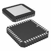
AD872AJE
Description
IC ADC 12BIT 10MSPS 44-CLCC
Manufacturer
Analog Devices Inc
Datasheet
1.AD872AJD.pdf
(20 pages)
Specifications of AD872AJE
Rohs Status
RoHS non-compliant
Number Of Bits
12
Sampling Rate (per Second)
10M
Data Interface
Parallel
Number Of Converters
7
Power Dissipation (max)
1.3W
Voltage Supply Source
Analog and Digital, Dual ±
Operating Temperature
0°C ~ 70°C
Mounting Type
Surface Mount
Package / Case
44-CLCC
Available stocks
Company
Part Number
Manufacturer
Quantity
Price


AD872A
ANALOG SUPPLIES AND GROUNDS
The AD872A features separate analog and digital supply and
ground pins, helping to minimize digital corruption of sensitive
analog signals. In general, AV
should be decoupled to AGND, the analog common, as close to
the chip as physically possible. Care has been taken to minimize
the signal dependence of the power supply currents; however,
the analog supply currents will be proportional to the reference
input. With REFIN at 2.5 V, the typical current into AV
85 mA, while the typical current out of AV
cally, 30 mA will flow into the AGND pin.
Careful design and the use of differential circuitry provide the
AD872A with excellent rejection of power supply noise over a
wide range of frequencies, as illustrated in Figure 29.
Figure 30 shows the degradation in SNR resulting from 100 mV
of power supply ripple at various frequencies. As Figure 30
shows, careful decoupling is required to realize the specified dy-
namic performance. Figure 34 demonstrates the recommended
decoupling strategy for the supply pins. Note that in extremely
noisy environments, a more elaborate supply filtering scheme
may be necessary.
100 mV p-p Signal on Power Supplies
Figure 29. Power Supply Rejection vs. Frequency,
(f
Figure 30. SNR vs. Supply Noise Frequency
–100
IN
–75
–80
–85
–90
–95
70
65
60
55
50
10
= 1 MHz)
10
4
4
10
10
5
5
FREQUENCY – Hz
FREQUENCY – Hz
SS
and AV
DD
10
10
, the analog supplies,
6
SS
6
AV
AV
DV
is 115 mA. Typi-
SS
DD
DD
AV
DD
DV
AV
DD
SS
10
10
DD
7
7
is
–14–
DIGITAL SUPPLIES AND GROUNDS
The digital activity on the AD872A chip falls into two general
categories: CMOS correction logic, and CMOS output drivers.
The internal correction logic draws relatively small surges of
current, mainly during the clock transitions; in the 44-terminal
package, these currents flow through pins DGND and DV
The output drivers draw large current impulses while the output
bits are changing. The size and duration of these currents are a
function of the load on the output bits: large capacitive loads are
to be avoided. In the 44-terminal package, the output drivers are
supplied through dedicated pins DRGND and DRV
count constraints in the 28-lead packages require that the digital
and driver supplies share package pins (although they have sepa-
rate bond wires and on-chip routing). The decoupling shown in
Figure 34 is appropriate for a reasonable capacitive load on the
digital outputs (typically 20 pF on each pin). Applications
involving greater digital loads should consider increasing the
digital decoupling proportionately, and/or using external buffers/
latches.
APPLICATIONS
OPTIONAL ZERO AND GAIN TRIM
The AD872A is factory trimmed to minimize zero error, gain
error and linearity errors. In some applications the zero and gain
errors of the AD872A need to be externally adjusted to zero. If
required, both zero error and gain error can be trimmed with ex-
ternal potentiometers as shown in Figure 31. Note that gain er-
ror adjustments must be made with an external reference.
Zero trim should be adjusted first. Connect V
adjust the 10 k potentiometer such that a nominal digital out-
put code of 0000 0000 0000 (twos complement output) exists.
Note that the zero trim should be decoupled and that the accu-
racy of the 2.5 V reference signals will directly affect the offset.
Gain error may then be calibrated by adjusting the REF IN
voltage. The REF IN voltage should be adjusted such that a
+1 V input on V
1111 1111 (twos complement output).
DIGITAL OFFSET CORRECTION
The AD872A provides differential inputs that may be used to
correct any offset voltages on the analog input. For applications
where the input signal contains a dc offset, it may be advanta-
geous to apply a nulling voltage to the V
voltage equal to the dc offset will maximize the full-scale input
range and therefore the dynamic range. Offsets ranging from
–0.7 V to +0.5 V can be corrected.
10k
+2.5V
–2.5V
10 F
(a) ZERO TRIM
Figure 31. Zero and Gain Error Trims
INA
0.1 F
results in the digital output code 01111
V
AD872A
INB
REF43
TRIM
V
OUT
INB
(b) GAIN TRIM
input. Applying a
INA
to ground and
100k
DD
. Pin
REF IN
REV. A
AD872A
DD
.
Related parts for AD872AJE
Image
Part Number
Description
Manufacturer
Datasheet
Request
R

Part Number:
Description:
±1.7g Dual-Axis IMEMS Accelerometer Evaluation Board
Manufacturer:
Analog Devices Inc
Datasheet:

Part Number:
Description:
Inertial Sensor Evaluation System
Manufacturer:
Analog Devices Inc
Datasheet:
Part Number:
Description:
Manufacturer:
Analog Devices Inc
Datasheet:
Part Number:
Description:
Manufacturer:
Analog Devices Inc
Datasheet:
Part Number:
Description:
Manufacturer:
Analog Devices Inc
Datasheet:
Part Number:
Description:
Manufacturer:
Analog Devices Inc
Datasheet:
Part Number:
Description:
Manufacturer:
Analog Devices Inc
Datasheet:
Part Number:
Description:
Manufacturer:
Analog Devices Inc
Datasheet:
Part Number:
Description:
Manufacturer:
Analog Devices Inc
Datasheet:
Part Number:
Description:
Manufacturer:
Analog Devices Inc
Datasheet:
Part Number:
Description:
Manufacturer:
Analog Devices Inc
Datasheet:
Part Number:
Description:
Manufacturer:
Analog Devices Inc
Datasheet:
Part Number:
Description:
Manufacturer:
Analog Devices Inc
Datasheet: