AD7846JP Analog Devices Inc, AD7846JP Datasheet - Page 7
AD7846JP
Manufacturer Part Number
AD7846JP
Description
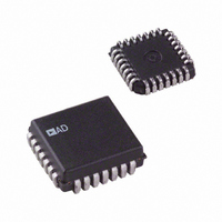
IC DAC 16BIT LC2MOS VOUT 28PLCC
Manufacturer
Analog Devices Inc
Datasheet
1.AD7846JPZ.pdf
(24 pages)
Specifications of AD7846JP
Data Interface
Parallel
Rohs Status
RoHS non-compliant
Settling Time
7µs
Number Of Bits
16
Number Of Converters
1
Voltage Supply Source
Dual ±
Power Dissipation (max)
100mW
Operating Temperature
0°C ~ 70°C
Mounting Type
Surface Mount
Package / Case
28-LCC (J-Lead)
Resolution (bits)
16bit
Sampling Rate
143kSPS
Input Channel Type
Parallel
Supply Voltage Range - Digital
4.75V To 5.25V
Supply Current
5mA
Digital Ic Case Style
LCC
Lead Free Status / RoHS Status
Contains lead / RoHS non-compliant
Available stocks
Company
Part Number
Manufacturer
Quantity
Price
Company:

Part Number:
AD7846JP
Manufacturer:
AD
Quantity:
1 980
Company:
Part Number:
AD7846JP
Manufacturer:
AD
Quantity:
5 510
Part Number:
AD7846JP
Manufacturer:
ADI/亚德诺
Quantity:
20 000
Company:
Part Number:
AD7846JP-REEL
Manufacturer:
AD
Quantity:
5 510
Company:
Part Number:
AD7846JP-REEL
Manufacturer:
LT
Quantity:
5 510
Company:
Part Number:
AD7846JP-REEL
Manufacturer:
Analog Devices Inc
Quantity:
10 000
Company:
Part Number:
AD7846JPZ
Manufacturer:
Analog Devices Inc
Quantity:
10 000
Part Number:
AD7846JPZ
Manufacturer:
ADI/亚德诺
Quantity:
20 000
Company:
Part Number:
AD7846JPZ-REEL
Manufacturer:
Analog Devices Inc
Quantity:
10 000


PIN CONFIGURATIONS AND FUNCTION DESCRIPTIONS
Table 5. Pin Function Descriptions
Pin
1 to 3
4
5
6
7
8
9
10 to 19
20
21
22
23
24
25
26 to 28
Table 6. Output Voltage Ranges
Output Range
0 V to +5 V
0 V to +10 V
+5 V to −5 V
+5 V to −5 V
+10 V to −10 V
Mnemonic
DB2 to DB0
V
V
R
V
V
V
DB15 to DB6
DGND
V
R/W
CS
CLR
LDAC
DB5 to DB3
DD
OUT
IN
REF+
REF−
SS
CC
V
V
V
DB15
DB14
DB13
DB12
DB11
Figure 7. PDIP Pin Configuration
REF+
REF–
DB2
DB1
DB0
V
OUT
V
R
DD
SS
IN
10
11
12
13
14
1
2
3
4
5
6
7
8
9
(Not to Scale)
Description
Positive Supply for Analog Circuitry. This is +15 V nominal.
DAC Output Voltage.
Input to Summing Resistor of DAC Output Amplifier. This is used to select output voltage ranges. See Table 6.
V
V
specified for both conditions.
Negative Supply for the Analog Circuitry. This is −15 V nominal.
Data I/Os. DB15 is MSB.
Ground for Digital Circuitry.
Positive Supply for Digital Circuitry. This is +5 V nominal.
R/W Input. This pin can be used to load data to the DAC or to read back the DAC latch contents.
Chip Select Input. This pin selects the device.
Clear Input. The DAC can be cleared to 000…000 or 100…000. See Table 7.
Asynchronous Load Input to DAC.
Data I/Os.
Data I/Os. DB0 is LSB.
AD7846
TOP VIEW
REF+
REF−
Input. The DAC is specified for V
Input. For unipolar operation connect V
28
27
26
25
24
23
22
21
20
19
18
17
16
15
DB3
DB4
DB5
LDAC
CLR
CS
R/W
V
DGND
DB6
DB7
DB8
DB9
DB10
CC
V
+5 V
+5 V
+5 V
+5 V
+5 V
REF+
Rev. G | Page 7 of 24
REF+
= +5 V.
REF−
to 0 V, and for bipolar operation connect it to −5 V. The device is
V
0 V
0 V
−5 V
0 V
−5 V
V
V
REF−
DB15
DB14
V
REF+
REF–
OUT
V
R
SS
IN
Figure 8. CERDIP Pin Configuration
10
11
5
6
7
8
9
12 13 14 15 16
4
3
(Not to Scale)
AD7846
TOP VIEW
2
1
PIN 1
IDENTIFIER
28 27 26
17 18
R
V
0 V
V
+5 V
0 V
OUT
OUT
IN
25
24
23
22
21
20
19
LDAC
CLR
CS
R/W
DGND
DB6
V
CC
AD7846
Related parts for AD7846JP
Image
Part Number
Description
Manufacturer
Datasheet
Request
R

Part Number:
Description:
±1.7g Dual-Axis IMEMS Accelerometer Evaluation Board
Manufacturer:
Analog Devices Inc
Datasheet:

Part Number:
Description:
Inertial Sensor Evaluation System
Manufacturer:
Analog Devices Inc
Datasheet:
Part Number:
Description:
Manufacturer:
Analog Devices Inc
Datasheet:
Part Number:
Description:
Manufacturer:
Analog Devices Inc
Datasheet:
Part Number:
Description:
Manufacturer:
Analog Devices Inc
Datasheet:
Part Number:
Description:
Manufacturer:
Analog Devices Inc
Datasheet:
Part Number:
Description:
Manufacturer:
Analog Devices Inc
Datasheet:
Part Number:
Description:
Manufacturer:
Analog Devices Inc
Datasheet:
Part Number:
Description:
Manufacturer:
Analog Devices Inc
Datasheet:
Part Number:
Description:
Manufacturer:
Analog Devices Inc
Datasheet:
Part Number:
Description:
Manufacturer:
Analog Devices Inc
Datasheet:
Part Number:
Description:
Manufacturer:
Analog Devices Inc
Datasheet:
Part Number:
Description:
Manufacturer:
Analog Devices Inc
Datasheet: