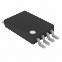
DS1851E-010+ Maxim Integrated Products, DS1851E-010+ Datasheet - Page 10

DS1851E-010+
Manufacturer Part Number
DS1851E-010+
Description
IC DAC DUAL NV TEMP CNTRL 8TSSOP
Manufacturer
Maxim Integrated Products
Datasheet
1.DS1851E-010TR.pdf
(18 pages)
Specifications of DS1851E-010+
Number Of Bits
8
Data Interface
Serial
Number Of Converters
2
Voltage Supply Source
Single Supply
Operating Temperature
-40°C ~ 95°C
Mounting Type
Surface Mount
Package / Case
8-TSSOP
Lead Free Status / RoHS Status
Lead free / RoHS Compliant
Power Dissipation (max)
-
Settling Time
-
DS1851
Sequential Address Read
Sequential reads are initiated by either a current address read or a random address read. After the master
receives the first data byte, the master responds with an acknowledge. As long as the DS1851 receives
this acknowledge after a byte is read, the master may clock out additional data words from the DS1851.
After reaching address FFh, it resets to address 00h.
The sequential read operation is terminated when the master initiates a STOP condition. The master does
not respond with a zero.
2-WIRE SERIAL PORT OPERATION
The 2-wire serial port interface supports a bidirectional data transmission protocol with device
addressing. A device that sends data on the bus is defined as a transmitter, and a device receiving data as
a receiver. The device that controls the message is called a “master.” The devices that are controlled by
the master are “slaves.” The bus must be controlled by a master device that generates the serial clock
(SCL), controls the bus access, and generates the START and STOP conditions. The DS1851 operates as
a slave on the 2-wire bus. Connections to the bus are made via the open-drain I/O lines, SDA and SCL.
The following I/O terminals control the 2-wire serial port: SDA and SCL. Timing diagrams for the 2-wire
serial port can be found in Figures 3 and 4. Timing information for the 2-wire serial port is provided in
the AC Electrical Characteristics table for 2-wire serial communications.
The following bus protocol has been defined:
Data transfer may be initiated only when the bus is not busy.
During data transfer, the data line must remain stable whenever the clock line is high. Changes in the
data line while the clock line is high will be interpreted as control signals.
Accordingly, the following bus conditions have been defined:
Bus not busy: Both data and clock lines remain high.
Start data transfer: A change in the state of the data line from high to low while the clock is high
defines a START condition.
Stop data transfer: A change in the state of the data line from low to high while the clock line is high
defines the STOP condition.
10 of 18


